Simrad R5000 Operator's Manual
Radar system
Hide thumbs
Also See for R5000:
- Commissioning manual (49 pages) ,
- Installation manual (27 pages) ,
- Quick manual (4 pages)
Table of Contents
Advertisement
Advertisement
Table of Contents

Related Manuals for Simrad R5000


Summary of Contents for Simrad R5000
- Page 1 R5000 Radar system Operator Manual ENGLISH www.navico.com/commercial...
- Page 3 About this manual Intended audience This manual is written for system operators. The manual assumes that the reader has basic knowledge about this type of equipment with regards to: • operation • nautical terminology and practices Preface | R5000 Operator manual...
- Page 4 The manual will continuously be updated to match new software releases. The latest available manual version can be downloaded from the product website on: www.navico-commercial.com Change log Part no Date and description 2018-Sept-19 988-12294-001 First version. 2018-Nov-01 988-12294-002 Updated to match software release. Preface | R5000 Operator manual...
- Page 5 Only reading these operating instructions cannot replace such training. Persons authorized to operate, maintain and troubleshoot the system are instructed and trained by Simrad. Persons operating or servicing this radar system must be familiar with the general safety regulations and specific safety systems, and they must have passed all required training.
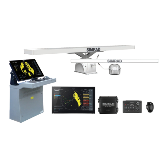
- Page 6 25 KW Transceiver 6' X-band Antenna 25 KW Transceiver 9' X-band Antenna 25 KW Transceiver 0.05 12' X-band Antenna 30 KW Transceiver 12' S-band Antenna X-Ray radiation This radar system does not generate X-ray radiation. Preface | R5000 Operator manual...
-
Page 7: Table Of Contents
Sea anti-clutter Rain anti-clutter Tuning the radar sensor 30 Radar view options Target trails and past position Radar orientation Radar motion mode Offsetting the PPI center Vectors Cursor bearings Setting the brilliance for panel items Contents | R5000 Operator manual... - Page 8 Manually changing the trial maneuver settings 58 Maintenance General Performance monitor Radar data 60 The alert system Type of alerts Alert categories Alert notifications The Alerts dialog External bridge alert systems Alphabetic alert list Operating modes fallback Contents | R5000 Operator manual...
- Page 9 66 Menu overview Main menu Settings menu 69 O2000/O5000 Trackball, key function comparison 70 Target symbols 73 Terms and abbreviations 78 Technical specifications General Performance Display features Target tracking Mapping Contents | R5000 Operator manual...
-
Page 10: Introduction
- O5000 trackball unit - R5000 radar processor An R5000 system can be installed as a stand-alone radar system, or as an advanced installation with several sensors and control stations. In an advanced installation, each radar sensor has a control station directly wired to it. This control station will be the radar sensor's default master controller. - Page 11 R5000 System installation manual Mechanical installation and wiring, technical specifications and mechanical drawings for all system components. Intended audience: Shipyard installation personnel. R5000 Configuration manual System setup/configuration and commissioning of the system. Intended audience: Installation and service engineers. Introduction | R5000 Operator manual...
-
Page 12: Operating The System
• Press to select • Rotate to scroll Display selected Quick access button Select pop-up options button's pop-up AIS target Activate/deactivate Display target menu No action Radar target Acquire target O2000 front controls Operating the system | R5000 Operator manual... - Page 13 Mark/MOB key. Not used for R5000 Unit under command LEDs. Not used for R5000 Display key. Used for configuration of the O2000. Not used for operating the R5000 EBL/VRM key. Press once to toggle EBL/VRM markers On/Off. Re-press to display the EBL/VRM pop-up.
-
Page 14: M5000 Monitor Keys
Solid on: standby mode, or no video source • Flashing: monitor booting or upgrading Menu key • Press and hold to activate the OSD menu For more information, refer to the separate documentation for the monitor. Operating the system | R5000 Operator manual... -
Page 15: The User Interface
Range and bearing from the vessel to the cursor position. Also including position information if a position source is available. Alerts panel List of all active alerts. Signal indicators Gauges for signal processing and indicators for radar functions. System information Range, mode and pulse details. The user interface | R5000 Operator manual... -
Page 16: Ppi Symbols
To use the trackball mouse to operate the menu: • Use the scroll wheel to move up and down in a menu • Use the left key to access a submenu, to toggle options or to confirm a selection The user interface | R5000 Operator manual... -
Page 17: The Settings Dialog
If the antenna position deviates from the CCRP this will be shown on the image. Vessel symbol at large range scale Vessel symbol at small range scale Units of measure settings The user interface | R5000 Operator manual... -
Page 18: Radar Video Palettes
If the virtual keyboard is inactive for 10 seconds it will automatically close. Complete the entry and close the dialog by selecting the virtual enter key. Remove the virtual keyboard without saving by pressing the exit key. The user interface | R5000 Operator manual... -
Page 19: Basic Operation
Press and hold the standby/brilliance key to turn the R5000 radar processor and the monitor to standby mode. The radar sensor is turned into standby mode only if R5000 is controlling it (connected as master). If it is in slave/clone mode, the sensor will continue transmitting. -
Page 20: Using The Cursor
The table shows stabilization modes available for each speed source type. Any restrictions for a source are detailed under each speed source description in the following sections. Stabilization mode Speed source Restrictions available Speed LOG (Single axis) None Basic operation | R5000 Operator manual... - Page 21 The reference echoes should never be used to calculate relative speed. This data is not following a speed change with adequate accuracy for an anti-collision system. Basic operation | R5000 Operator manual...
-
Page 22: Target Tracking
The acknowledged alert is not moved to its new position in the sort order until there has been 2 seconds without any alerts being acknowledged. For more details, refer to "The alert system" on page 60. Basic operation | R5000 Operator manual... -
Page 23: Applying Default Control Settings
The predefined values are defined in the radar requirements standard. Refer "Customizing radar control settings" on page 54. Screen capture To take a screen capture: • Simultaneously press the enter key and the standby/brilliance key Screen captures are saved to internal memory. Basic operation | R5000 Operator manual... -
Page 24: The Interswitch Function
The control station can have different control modes for the sensors connected via the interswitch network. The illustration shows an example of control modes for an installation with 2 sensors and 4 control stations. Master mode Master mode requested Slave mode Clone mode The Interswitch function | R5000 Operator manual... -
Page 25: Changing Control Mode
There can be multiple clone stations for each control station simultaneously. Changing control mode To request a control mode for a sensor from a control station: Select the status you want to request (A) Assign the status to a sensor (B) The Interswitch function | R5000 Operator manual... -
Page 26: Indication Of Control Status
You can also request master or slave control mode from the sensor network status dialog. Indication of control status The control station’s operational mode (A) for the active radar sensor (B) is indicated in the system information panel. The Interswitch function | R5000 Operator manual... -
Page 27: Adjusting The Radar Image
When you increase the value, the sensitivity of the near field clutter caused by waves is reduced. If the value is increased too much, both sea clutter and Adjusting the radar image | R5000 Operator manual... -
Page 28: Rain Anti-Clutter
As an example for long pulse length: a target that can be detected at 10 NM can only be detected on 3 NM with 16 mm rain. Adjusting the radar image | R5000 Operator manual... -
Page 29: Tuning The Radar Sensor
Select the tune quick access key to activate the function, then use the scroll wheel or the rotary knob to adjust the setting • Press the left mouse key twice to turn ON/OFF the automatic option Adjusting the radar image | R5000 Operator manual... -
Page 30: Radar View Options
In relative motion your vessel remains in a fixed location on the Radar PPI, and all other objects move relative to your position. You select the position of the fixed location as described in "Offsetting the PPI center" on page 31. Radar view options | R5000 Operator manual... -
Page 31: Offsetting The Ppi Center
PPI center is placed at 70% of the radius of the PPI, 180° opposite the top of the display. Ú Note: The look ahead option is only available for heading up radar orientation. Radar view options | R5000 Operator manual... -
Page 32: Vectors
You can select to show the cursor bearings as true or relative to own vessel. Ú Note: True can only be selected when a gyro is available. Setting the brilliance for panel items The brilliance can be set individually for the various panel items. Radar view options | R5000 Operator manual... -
Page 33: Targets
When you select a radar or an AIS target, the target symbol changes to the selected target icon, and the target panel changes to show detailed information for the selected target Targets | R5000 Operator manual... -
Page 34: Defining Dangerous Vessels
After 3 minutes the symbol will become steady, and all the data fields of selected targets will be available. The target symbol will change to the tracked radar target symbol. The above time references represent worst case situations. In a stable situation the radar target information is available immediately. Targets | R5000 Operator manual... - Page 35 A target trail indicates the target movement by leaving an afterglow, gradually reducing the intensity over time. Target trails show where a target used to be, and the function is useful for quickly assessing the movement of targets relative to your own vessel. Targets | R5000 Operator manual...
- Page 36 A second trace echo is an echo received from a distant target, received after the following pulse has been transmitted. Second trace echoes are present only under abnormal atmospheric conditions, or in condition of super-refraction. Targets | R5000 Operator manual...
-
Page 37: Radar Sart
Radar-SART far from own vessel (range: 24 NM) Radar-SART close to own vessel (range: 3 NM) Position of SART Echo from SART Targets | R5000 Operator manual... -
Page 38: Racons
Morse character beginning with a dash for identification. The inherent delay in the racon causes the displayed response to appear behind the echo from the structure on which the racon is mounted (A). Targets | R5000 Operator manual... -
Page 39: Ais Targets
Only activated AIS targets are listed in the target panel. Activated AIS targets are always processed against CPA/TCPA limits, and are defined as dangerous targets if the CPA/TCPA limits are exceeded. Targets | R5000 Operator manual... - Page 40 AIS target with heading line and SOG/COG (dashed line), and with indicated turn direction AIS target with true scaled outlines AIS target with past track Selected AIS target, indicated with a square (dashed line) around the target symbol Targets | R5000 Operator manual...
-
Page 41: Ais And Radar Target Association
Associated targets - using radar data This function is useful for reducing the number of AIS symbols and radar targets on the PPI. Too many targets could clutter the screen and result in dangerous situations. The function Targets | R5000 Operator manual... -
Page 42: Displaying Target Information
Detailed information about an AIS target is available from the AIS vessels details dialog. To display the dialog: • select the AIS additional information option in the target menu • select an AIS target in the vessels dialog Targets | R5000 Operator manual... -
Page 43: Training Simulator
Training Tgt TCPA Out of Range: if the difference between theoretical and target displayed CPA is greater than 30sec The radar will return to default operation as soon as the training option is turned off from the menu. Targets | R5000 Operator manual... -
Page 44: Navigation Tools
The tracking zone lines turns to dashed lines to indicate that you are in edit mode Define the guard zone options: A: Range, relative to vessel center B: Depth C: Bearing, relative to vessel heading or to North D: Width Navigation tools | R5000 Operator manual... -
Page 45: Parallel Index Lines
- The change is immediately committed and shown on the image Press the exit key or the right arrow key to leave the edit mode Ú Note: Max range for a bearing line is 12 NM. Navigation tools | R5000 Operator manual... -
Page 46: Ebl/Vrm Markers
• EBM/VRM1 is cyan • EBL/VRM2 is blue The EBL presentation can be defined with true or relative presentation: Navigation tools | R5000 Operator manual... - Page 47 The text in the EBL/VRM short-cut button and the EBL/VRM marker's line width indicate which item that is in edit mode. EBL/VRM2 ON, EBL/VRM1 and 2 ON, EBL/VRM1 and 2 ON, function not in edit mode EBL1 in edit mode VRM1 in edit mode Navigation tools | R5000 Operator manual...
-
Page 48: Measuring Range And Bearing
System Information area on the radar image. The range scales, the related distance between the range rings and number of rings are: Range (NM) Range rings interval (NM) Number of range rings 1/8 (200m) 1/40 (100m) 1/20 1/10 Navigation tools | R5000 Operator manual... - Page 49 - Range and bearing from the EBL/VRM marker's center to cursor position is now displayed in the Markers panel You can reset the EBL/VRM marker's center to vessel position by selecting the reset offset option in the EBL/VRM pop-up. Navigation tools | R5000 Operator manual...
-
Page 50: Maps
Geographic maps cannot be created or imported if EPFS (Electronic Position Fixing System) or Gyro is unavailable or failing. A geographic map cannot be displayed if the ship is too far from the area of the map. Maps | R5000 Operator manual... -
Page 51: Map Colors And Symbols
Select the map name to display the keyboard if you want to give the map a unique name • Set the map reference • Select the menu option to enter map details. See "Modifying a map" on page 52. Maps | R5000 Operator manual... -
Page 52: Saving A Map
Press the enter key or the right mouse key to display the map edit menu, then select the edit option Continue positioning the cursor and selecting the edit option until all changes are done Press the exit key to leave the edit mode Maps | R5000 Operator manual... -
Page 53: Exporting Maps
Importing maps Compatible maps created on other units can be imported to the system. Imported maps are added to the units' non-volatile memory, and the maps are added to the list of loaded maps. Maps | R5000 Operator manual... -
Page 54: Customizing Radar Control Settings
Graphical AIS reported target display Radar and AIS target function Association On Operational alarms (except collision warnings) Collision warning On (limits CPS 2 NM, TCPA 12 minutes) Display of maps, navigation lines and routes Last settings Customizing radar control settings | R5000 Operator manual... -
Page 55: Advanced Options
Change the speed of the radar antenna rotation from 20 RPM in standard mode to 40 RPM in fast scan mode. This option gives faster target updates. Ú Note: The fast scan option is not available for 12 feet X-band antennas and for HSC radar sensors. Advanced options | R5000 Operator manual... -
Page 56: Trial Maneuver
The following indications are used to indicate that a target's position is a dangerous at the end of the trial maneuver: • flashing red target symbol • yellow color in the trial maneuver panel • a relevant alarm Trial maneuver | R5000 Operator manual... -
Page 57: Starting And Stopping The Trial Maneuver
The default trial maneuver settings are defined during commissioning of the vessel. The trial maneuver settings menu remains open after the function is started. If a maneuver is considered dangerous, you can adjust the speed and/or course to see how to avoid a dangerous situation. Trial maneuver | R5000 Operator manual... -
Page 58: Maintenance
If the receiver noise figure degradation is more than 10 dB, it is not possible to distinguish the performance monitor ring from the background noise. Ú Note: If sector blanking is enabled, the performance monitor ring will have missing sectors in the sector blanking areas. Maintenance | R5000 Operator manual... -
Page 59: Radar Data
Radar data The Radar data dialog displays status for vital radar components. The system displays an alert when the magnetron has to be replaced. For replacement procedures refer to the separate Commissioning manual. Maintenance | R5000 Operator manual... -
Page 60: The Alert System
Each alert in the list has to be acknowledged individually. The table below shows alert icons and behavior depending on alert state. The alert system | R5000 Operator manual... - Page 61 Active - responsibility transferred • No audible signal • Flashing symbol and descriptive Rectified - not text acknowledged • No audible signal • Steady symbol and descriptive text Caution Active • No audible signal The alert system | R5000 Operator manual...
- Page 62 Active - responsibility transferred • No audible signal • Flashing symbol and descriptive Rectified - not text acknowledged • No audible signal • Steady symbol and descriptive text Caution Active • No audible signal The alert system | R5000 Operator manual...
-
Page 63: The Alerts Dialog
If a BNWAS is connected to the system, the system outputs an EVE sentence to the BNWAS when a user interaction with the system occurs. The EVE sentence remotely resets the BNWAS timer to confirm wheelhouse crew activity. The alert system | R5000 Operator manual... -
Page 64: Alphabetic Alert List
SPD Tran. Axis FAIL Speed transversal axis data failure STW FAIL Speed Through Water failure Test alarm The Test alarm is enabled to verify audible alarm operation TGT in GZ Tracked target # within the vessel's guard zone The alert system | R5000 Operator manual... -
Page 65: Operating Modes Fallback
Possible to • Acquiring/tracking radar targets display target Radar video • True motion/ True trails RADAR FAIL information input failure • Radar video presentation based on AIS data • AIS input failure AIS FAIL The alert system | R5000 Operator manual... -
Page 66: Menu Overview
Save settings > Load settings > TT/AIS > Cancel all Cancel selected target Lost warning Range CPA/TCPA limit ... AIS > Data ... Target ASSOC > Training Speed source > Stabilization Source Manual speed Drift/Set Drift Menu overview | R5000 Operator manual... -
Page 67: Settings Menu
Access control Service mode Enter password ... System Key beeps Time ... Remote controller Restore defaults ... Files ... Advanced ... Reboot device Registration ... About Radar Installation Radar video palette Target trails palette Menu overview | R5000 Operator manual... - Page 68 Control display units ... Sources ... Priorities table ... Device list Diagnostics NMEA 0183 > Own ship Setup ... MMSI Own ship AIS data Trial maneuver Simulator Simulate Demo mode Files ... Advanced ... Menu overview | R5000 Operator manual...
-
Page 69: O2000/O5000 Trackball, Key Function Comparison
Activate/de-activate AIS Left key Enter key - single press target Acquire radar target Left key Enter key - single press Display target menu Right key Enter key - press and hold O2000/O5000 Trackball, key function comparison | R5000 Operator manual... -
Page 70: Target Symbols
Associated target - using AIS data Associated target - using radar data Physical AIS AtoN, basic shape (AIS aids to navigation) Physical AIS AtoN - East cardinal mark Physical AIS AtoN - Emergency wreck mark Target symbols | R5000 Operator manual... - Page 71 The symbol is located at the last received position from the target Radar target - Selected, indicated with a square (dotted line) around the target symbol Radar target - Tracked, with velocity vector Target symbols | R5000 Operator manual...
- Page 72 Virtual AIS AtoN - Safe water Virtual AIS AtoN - South cardinal mark Virtual AIS AtoN - Special mark Virtual AIS AtoN - Starboard hand mark Virtual AIS AtoN - West cardinal mark Missing Virtual AIS AtoN Missing Target symbols | R5000 Operator manual...
-
Page 73: Terms And Abbreviations
Course Over Ground CONT Contrast Closest Point Of Approach Central Processing Unit Course Course To Steer CURS Cursor DAY/NT Day/Night DECR Decrease Degrees Delete DGPS Differential Gps DISP Display DIST Distance DPTH Depth Terms and abbreviations | R5000 Operator manual... - Page 74 Global Positioning System Guard Zone H UP Head Up Heading Heading Line Hours Input/Output Integrated Bridge System Identification Input INIT Initialization Integrated Navigation System Interference Rejection IRCS Integrated Radio Communication System Interswitch Kilometer Knots Label Terms and abbreviations | R5000 Operator manual...
- Page 75 Anti Clutter Rain RCDS Raster Chart Display System Echo Reference REF SOG Echo Reference Speed REL or R Relative Relative Motion RM (R) Relative Motion (Relative Trails) RM (T) Relative Motion (True Trails) Terms and abbreviations | R5000 Operator manual...
- Page 76 Target threshold True Motion Transponder TRIAL Trial Maneuver TRIG Trigger Pulse Track TRKG Tracking Tracking Time To Go Target separation TWOL Time To Wheel Over Line Transmit, Transmitter TX/RX Transceiver Uninterruptible Power Supply Terms and abbreviations | R5000 Operator manual...
- Page 77 Variable Range Marker Vessel Traffic Services Wheel Over Line Wheel Over Point Terms and abbreviations | R5000 Operator manual...
-
Page 78: Technical Specifications
Short pulse 3000 Hz Medium pulse 1500 Hz Long pulse 750 Hz Modulator MOSFET Solid State IF amplifier Logarithmic IF dynamic 95 dB IF center frequency 60 MHz IF bandwidth Short pulse 24 MHz Technical specifications | R5000 Operator manual... -
Page 79: Display Features
Up to 75% of range scale in use Polar and Geographical coordinates, Cursor continuously displayed when cursor is activated Target tracking Acquisition Manual and automatic, up to 100 targets Tracking Manual and automatic, up to 100 targets Technical specifications | R5000 Operator manual... -
Page 80: Ais
Map storage • SD Card transfer available • Rotate Map adjustments • Shift Parallel index Four independent parallel index lines • Own ship data • Target tracking data Data readout • AIS target data Technical specifications | R5000 Operator manual... - Page 82 www.navico.com/commercial...
Need help?
Do you have a question about the R5000 and is the answer not in the manual?
Questions and answers