Table of Contents
Advertisement
Quick Links
Advertisement
Table of Contents

Related Manuals for Simrad NSS


Summary of Contents for Simrad NSS
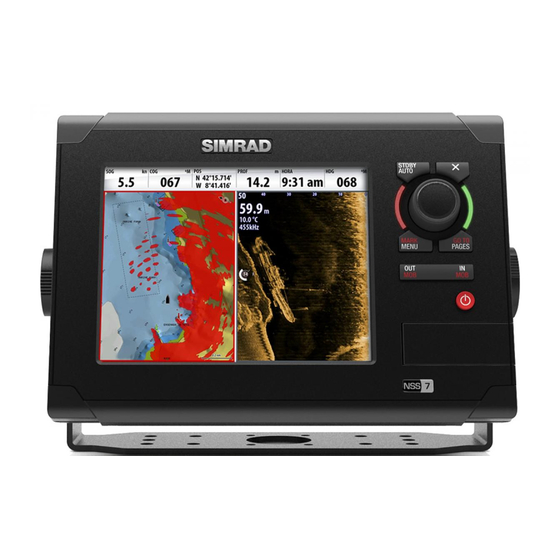
- Page 1 Operator Manual ENGLISH www.simrad-yachting.com...
-
Page 3: About This Manual
Declarations and conformance This equipment is intended for use in international waters as well as coastal sea areas ad- ministered by countries of the E.U. and E.E.A. For more information refer to the separate NSS Installation manual. About this manual This manual is a reference guide for operating the Simrad NSS systems. - Page 4 The software This manual is written for Simrad NSS Release to Market 1 (RTM1). Please check web site for details on release version. GOTO PAGES Note: The About dialog above is an example only and may not match the sw installed on your unit! The manual will be continuously updated to match new sw releases.
-
Page 5: Table Of Contents
Contents Introduction The NSS front panel and keys The NSS screen Basic operation The power key Using the touch screen Pages and panels The menus Dialog boxes Positioning a Man Over Board mark Charts The chart panel Chart scale Panning the chart... - Page 6 Using the NSS in an AP24/AP28 system Using the autopilot in an EVC system The autopilot settings panel Using the radar The radar panel The radar operational modes Using the cursor on the radar panel Optimizing the radar image Positioning the radar center...
- Page 7 Setting the appearance of the instrument bar Changing system settings Using the simulator Simulator mode Demo mode Selecting simulator source fi les Advanced simulator settings Maintenance Preventive maintenance Simple maintenance procedures Software upgrades Trouble shooting Backing up your system data Contents | NSS Operator Manual...
- Page 8 Menu and dialog overview Panel menus Goto menu Settings dialogs Index Contents | NSS Operator Manual...
-
Page 9: Introduction
Introduction The NSS front panel and keys SIMRAD STBY AUTO MARK GOTO MENU PAGES NSS 7 Touch screen Card reader door Micro-SD Card reader Used for optional Navionics or InsightHD chart data, software updates, transfer of user data and system backup. -
Page 10: The Nss Screen
The NSS screen Instrument bar See “Customizing Navigation and sensor info can be viewed in a user confi gurable instrument bar on top of your system” on page 82 your pages. for further information Panel button You can tap the text on this area to end an ongoing operation, e.g. to remove the cursor from the screen, to end route editing and to stop measuring distance. -
Page 11: Menu Panel Button
77 for system is running. When an alarm situation occurs, an Alarm dialog will pop up. further information If you have enabled the siren, an audible alarm will be activated when an alarm situation occurs. Introduction | NSS Operator Manual... - Page 12 fi nd function and fi les. If a CZone system is connected, this function is access from the Tools panel. Settings The Settings panel gives access to system and vessel setup, application settings, and to the simulator. 10 | Introduction | NSS Operator Manual...
-
Page 13: Basic Operation
Advanced power control Note: If the power key is released before shut-down is completed, the power off is cancelled. The NSS can be wired and confi gured to control the power of displays and A night mode which optimizes the color palette for low light conditions, is included. -
Page 14: The Menus
A virtual keyboard is operated by tapping the virtual keys. A dialog is closed by tapping the in the upper right corner or by pressing the key. 12 | Basic operation | NSS Operator Manual... -
Page 15: Positioning A Man Over Board Mark
• the NSS creates an active route to the MOB mark Cancel navigation The NSS will continue navigating towards the MOB point until the waypoint is reached or until you select to stop this navigation. Delete a MOB mark A MOB mark is deleted by selecting the MOB mark and then activating the menu. -
Page 16: Charts
On the panel you can plan and navigate routes, place waypoints, overlay a radar image or weather information, and display AIS targets. The NSS has diff erent embedded cartography depending on region. Units sold in America will include Insight cartography, while units sold in other regions will have embedded Navionics coastal (Silver) cartography split by region. -
Page 17: Using The Cursor On The Chart Panel
Cursor Information window Continue tapping the screen to position new measuring points You terminate the measuring function by pressing the key or the Finish measuring panel key. | 15 Charts | NSS Operator Manual... -
Page 18: Positioning The Chart On The Panel
It is not possible to scale the boat icon to match actual boat size, and the size remains the same independent on chart scaling. Zooming 3D charts You zoom the 3D chart by using the IN/OUT key. The rotary knob will not zoom 3D charts. 16 | Charts | NSS Operator Manual... -
Page 19: Insight Chart Options
This is the minimum information suffi cient for navigation Full This is all available information for the chart in use Look ahead This option centres the chart slightly forward of your vessel so that you can maximize your view ahead. | 17 Charts | NSS Operator Manual... -
Page 20: Navionics Chart Options
Photo overlay enables you to view satellite photo images of an area as an overlay on the chart. The availability of such photos is limited to certain regions. You can view photo overlays in either 2D or 3D modes. No Photo overlay Photo overlay, land only Full Photo overlay 18 | Charts | NSS Operator Manual... -
Page 21: The Chart Settings Panel
For optional chart panel settings, refer the illustration on page 14. Chart data The NSS can use Navionics Platinum Plus and TurboView via micro-SD Card Slot accessible from the front of the unit. Charts are shared over the network, so only one chart card per boat is required. - Page 22 Determines which icon to use on 3D charts. See “The boat icon” on page 16. Synchronize 2D/3D chart Links the position shown on one chart with the position shown on the other chart when a 2D and a 3D chart are shown side by side. 20 | Charts | NSS Operator Manual...
-
Page 23: Waypoints, Routes & Tracks
Note: The waypoint radius alarm must be toggled ON in the alarm panel to activate an alarm when your vessel comes within the defi ned radius. | 21 Waypoints, routes & tracks | NSS Operator Manual... -
Page 24: Routes
The automatic tracking function can be turned off from the Tracks panel described later in this section. 22 | Waypoints, routes & tracks | NSS Operator Manual... -
Page 25: The Waypoints, Route And Tracks Panels
The track is made up of a series of track points connected by line segments whose length depends on the frequency of track recording. You can select to position track points based on time settings, distance, or by letting the NSS system position a waypoint automatically when a course change is registered. -
Page 26: Navigating With The Nss
Navigating with the NSS The navigation function included in the NSS allows you to navigate towards the cursor position, a waypoint or along a predefi ned route. For information about positioning waypoints and creating routes, refer “Waypoints, routes & tracks” on page 22. -
Page 27: Navigating With Autopilot
Navigating with autopilot If an AC12, AC42 or an SG05 autopilot computer is connected to the system, autopilot functionality will be included in the NSS. When you start navigation on a system with autopilot functionality, you will be prompted to set the pilot to navigation mode. -
Page 28: Navigation Panels
Datum Most paper charts are made in the WGS84 format, which also is used by the NSS system. If your paper charts are in a diff erent format, you can change the datum settings accordingly to match your paper charts. -
Page 29: Position Panels
GPS position info Loran position info Data fi elds Position in lat. and lon. (GPS) or as Loran GRI and station values Time and date Speed over ground Course over ground | 27 Navigating with the NSS | NSS Operator Manual... -
Page 30: Using The Autopilot
STBY/AUTO key. Note: If the NSS is connected to an EVC system via the SG05, you can take manual control of the steering irrespective of the autopilot mode. Refer “Using the autopilot in an EVC system” on page 38. -
Page 31: The Autopilot Panel
Autopilot mode overview The autopilot has several steering modes. Number of modes and features within the mode depend on boat type and available inputs, as shown in table on the next page. | 29 Using the autopilot | NSS Operator Manual... - Page 32 30 | Using the autopilot | NSS Operator Manual...
-
Page 33: Controlling Steering Performance In Automatic Modes
The autopilot includes a number of automatic turn steering features for power boats when the pilot is in AUTO mode. The turn steering option will not be available if the boat type is set to sailboat - instead the tack/gybe feature is implemented. | 31 Using the autopilot | NSS Operator Manual... - Page 34 33 ft - 3281 ft 656 ft Initial radius 10 m - 1000 m 200 m -164 ft - +164 ft 66 ft Change of radius per turn -50 m - +50 m 20 m 32 | Using the autopilot | NSS Operator Manual...
- Page 35 The main course can be changed by turning the rotary knob. Turn parameter Range Change per step Default Course change 4° - 160° 28° 16 ft - 1641 ft 656 ft Radius 5 m – 500 m 200 m | 33 Using the autopilot | NSS Operator Manual...
- Page 36 Use the following process to initiate DCT steering; Ensure that you have depth reading on the NSS unit or on a separate depth instrument Steer the boat to the depth you want to track, and in the direction of the depth contour (main course)
-
Page 37: Nodrift Mode
The go to cursor option will only be available when the cursor is active on a Chart, Radar or Echosounder panel. For more information about navigating with the NSS refer to “Navigating with the NSS” on page 25. You can also start navigating from the autopilot menu. -
Page 38: Sailing With The Autopilot
Initiate wind steering as follows; Switch the Autopilot to AUTO mode Adjust the boat heading until wind angle is according to the angle you want to maintain Press the MENU key, and select Wind 36 | Using the autopilot | NSS Operator Manual... - Page 39 The tack prevent function in WIND mode has been implemented to avoid such situations. It will react immediately when the apparent wind angle becomes 5° less than the set minimum wind angle, and more rudder will be commanded. | 37 Using the autopilot | NSS Operator Manual...
-
Page 40: Wind Steering And Navigation
You can only unlock the remote stations from the AP24/AP28 unit in command. Using the autopilot in an EVC system When the NSS is connected to an EVC system via the SG05, you can take manual control of the steering irrespective of the autopilot mode. -
Page 41: The Autopilot Settings Panel
Locking an NSS unit If two NSS units are included in the system, the non-active NSS unit can be locked to prevent unauthorized operation of the autopilot. When the unit is locked this is indicated with a lock symbol and with text in the pop up. -
Page 42: Sailing Parameters
A low response level reduces the rudder activity and provides a more “loose” steering. A high response level increases the rudder activity and provides a more “tight” steering. A too high response level will make the boat start S-ing. 40 | Using the autopilot | NSS Operator Manual... - Page 43 This option displays an overview of all autopilot steering parameters, and you can adjust parameters if required. For more details, refer to the separate AC12/AC42 Installation manual. Installation Used for autopilot installation and commissioning. See the separate AC12/AC42 or SC05 Installation manual. | 41 Using the autopilot | NSS Operator Manual...
-
Page 44: Using The Radar
Radar symbology can be turned ON/OFF collectively from the Radar menu, or individually as described in “Radar settings panel” on page 49. The radar operational modes The radar’s operational modes are controlled from the NSS unit. The following modes are available: The power to the radar scanner is turned off... -
Page 45: Optimizing The Radar Image
Center Default setting. The radar PPI center is centered on the radar panel. Look Ahead Moves the radar PPI center to the bottom of the panel to give maximum view ahead. | 43 Using the radar | NSS Operator Manual... -
Page 46: Measuring Range And Bearing To A Target
You can position EBL/VRM by using the cursor, and edit the marker position as described below. When positioned, you can quickly turn the EBL/VRM on/off by tapping the relevant markers on the data bar. 44 | Using the radar | NSS Operator Manual... -
Page 47: Setting A Guard Zone Around Your Vessel
The threshold sets required signal strength for the lowest radar signals. Radar returns below this limit will be fi ltered and not displayed. Default value: 30%. Target boost The target boost option is used for increasing the size of radar targets. | 45 Using the radar | NSS Operator Manual... -
Page 48: Radar Orientation
Rotates the radar image to display the current navigation course directly up. This option works only when the NSS is navigating an active route. If you are not navigating an active route the heading up orientation will be used until the navigation function is started. -
Page 49: Marpa Targets
MARPA targets If the NSS includes a heading sensor, the MARPA function (Mini Automatic Radar Plotting Aid) can be used to track up to tem radar targets. You can defi ne alarms to notify you if a target gets too close. Refer “MARPA target settings” on page 47. -
Page 50: Radar Overlay
You can overlay the Radar image on the Chart. This can help you to easily interpret the radar image by correlating the radar targets with charted objects. When the radar overlay is selected, basic radar operational functions are available from the Chart panel’s menu. 48 | Using the radar | NSS Operator Manual... -
Page 51: Radar Settings Panel
Allows for adding target trails and guard zone indication around a MARPA target. Refer to description on previous pages. Installation The Installation option is used for Radar installation, described in the separate NSS Installation manual. | 49 Using the radar |... -
Page 52: The Echosounder
This option allows you to manually set both upper and lower range limits. The echosounder panel can be setup as a single view, or with split view where the left and the right side presents diff erent images. 50 | The echosounder | NSS Operator Manual... -
Page 53: Zooming
The scaling factor for the image on the left side of the panel is adjusted as described for the Zoom option. Echo frequency The NSS unit supports several transducer frequencies. Available frequencies depend on sounder module and which transducer model is connected. -
Page 54: Adjusting Color And Gain Settings
. You can pan the image history by dragging left/right on the screen. To resume normal scrolling, tap the Clear cursor panel button or press the key. 52 | The echosounder | NSS Operator Manual... -
Page 55: Placing A Mark On An Echosounder Image
Recording the echosounder data You can record echosounder data and save the fi le internally in the NSS unit, or on to a Micro- SD card inserted into the unit’s card reader. The function is activated from “The echosounder settings panel”, see page 55. -
Page 56: Echo Options
This will clearly separate fi sh and vegetation from the bottom. No bottom coloring Bottom coloring ON Optional echosounder image items Echosounder images can be turned on/off individually. Refer graphics on page 50. 54 | The echosounder | NSS Operator Manual... -
Page 57: Structurescan™ Overlay
Traditional fi sh echoes Fish symbols and depth indication StructureScan™ overlay When a StructureScan unit is connected to your NSS system, you can overlay a DownScan image on the regular echo image. When activated as described below, the echosounder menu will expand to include basic StructureScan options. -
Page 58: Overlay Downscan
Overlay downscan When a StructureScan unit is connected to your NSS system, you can overlay DownScan images on the regular echo image. When activated, the echosounder menu will expand to include basic StructureScan options. See “StructureScan™ overlay” described previously. Recording and viewing the echosounder data See page 53. -
Page 59: Structurescan
The DownScan image can also be added as an overlay to the traditional Echosounder image. For more information, refer to “StructureScan™ overlay” on page 56. DownScan Depth Temperature Range Frequency / zoom scale Upper range Color indicator Sea bed Lower range | 57 StructureScan™ | NSS Operator Manual... -
Page 60: Zooming
StructureScan supports two frequencies. 455 kHz is ideal for greater depth penetration and while 800 kHz provides better defi nition especially at shallower depths. Zooming You can use the keys to select zooming level on the StructureScan image. Zoom level is shown on the panel. 58 | StructureScan™ | NSS Operator Manual... -
Page 61: Adjusting The Color Settings
You can position a mark on a selected echosounder item by tapping the screen and then activating the menu. Note: Only marks positioned by using the cursor will include depth information. | 59 StructureScan™ | NSS Operator Manual... -
Page 62: Measuring Distance
Recording the StructureScan™ data You can record StructureScan data and save the fi le internally in the NSS unit, or onto a Micro- SD card as described in “Recording and viewing the echosounder data” on page 57. Structure options Structure palette Several display palettes with varying degrees of color and brightness are available. -
Page 63: The Instruments Panels
Select info to display Save your changes by using the menu or by tapping the Finish editing panel button. You can also use the rotary knob to select menu item and gauges. | 61 The Instruments panels | NSS Operator Manual... -
Page 64: Using Ais
You can defi ne alarms to notify you if an AIS target gets too close or if the target is lost. AIS vessels on a chart panel AIS vessels on a radar panel Target symbols The NSS system use the AIS target symbols shown below: Symbol Description Sleeping AIS target (not moving or at anchor). -
Page 65: Vessel Alarms
You need to have your own MMSI (Maritime Mobile Service Identity) number entered in the NSS system to be able to receive addressed messages from AIS and DSC vessels. It is also important to have the MMSI number entered to avoid seeing your own vessel as an AIS target on the chart. -
Page 66: Filtering The Targets
Filtering the targets All targets are by default shown on the display if an AIS device is connect to the NSS system. You can select to not show any targets, or to fi lter the icons based on security settings, distance and vessel speed. -
Page 67: Audio
Audio When the NSS is connected to a SonicHub server you can use your unit to control audio play- back from iPod, iPhone, USB mass storage device (mp3) and AM/FM radio. Before playing FM radio through the SonicHub, you must purchase a marine-grade AM/FM antenna. -
Page 68: Setting Up The Sonichub Speakers
By default the volume for all speaker zones are adjusted when you adjust the volume on an NSS unit. You can adjust each speaker zone individually from any NSS unit from the SonicHub Zones dialog. From this dialog you can also defi ne which zones that shall be altered when you increase/decrease the volume from the control unit. -
Page 69: Audio Playback
Saving a channel to the favorite list When the channel is tuned in, you can add the stations to your favorite list. All favorite channels can be viewed, selected and deleted from within this list. | 67 Audio | NSS Operator Manual... -
Page 70: Using Sirius Radio
You can lock selected Sirius channels from being broadcast unless an unlock code is entered. When the function is activated, a 4 digit code must be entered before the locking is activated. The same code must be entered before a locked channel can be released. 68 | Audio | NSS Operator Manual... -
Page 71: Siriusxm™ Weather (North America Only)
When connected to a Navico Weather Module WM-2, you can subscribe and include Sirius™ audio and Sirius™ Marine Weather Service on your NSS system (North America only). Sirius™ audio and weather service covers inland US waters and coastal areas into the Atlantic and Pacifi... -
Page 72: Weather Symbology
Hurricane (category 1-5) tracking; past (grey) - present (red) - future (yellow) Tropical disturbance/depression tracking; past (grey) - present (red) - future (yellow) Storm attributes Lightning Watch box location and warning Marine zone location 70 | SiriusXM™ weather (North America only) | NSS Operator Manual... -
Page 73: Weather Alarms
These statements are available for the entire Atlantic and the Eastern Pacifi c. Animating Sirius™ weather graphics The NSS records the weather information you have turned on, and this information can be used to animate past or future weather conditions. The amount of information available in the system depends on the amount of weather activity,- the more complex it is the less time will be available for animation. -
Page 74: Using Video
Setting up the video panel The video source NSS supports two video input channels. You can select to view one channel only, or to cycle the image between available video cameras. The cycle period can be set from 5 to 120 seconds. - Page 75 Video input can be set to display a mirrored image. This setting can be helpful for rear-facing cameras used to back-down the vessel. The video standard NSS supports NTSC and PAL video. The two channels are set up individually. Check the local video standard or the standard of your cameras. | 73...
-
Page 76: Bep Czone
BEP CZone The NSS system integrate with BEP’s CZone system used for controlling and monitoring a distributed power system on your vessel. A separate manual will be provided with your CZone system. Refer to this documentation and to the NSS Installation for how to install and confi gure the CZone system. -
Page 77: The Czone Info Panel
You can customize CZone dashboard by changing the data for each of the gauges. Available panels” on page 62 for editing options will depend on the type of gauge and which data sources are connected to further information. your system. | 75 BEP CZone | NSS Operator Manual... -
Page 78: The Alarm System
The alarm system The NSS system will continuously check for dangerous situations and system faults while the system is running. When an alarm situation occurs, an alarm message will pop up on the screen. If you have enabled the siren, the alarm message will be followed by an audible alarm, and the switch for external alarm will go active. -
Page 79: The Alarms Dialog
The alarms can be setup in the Alarms dialog. This dialog also includes information about active alarms and alarm history. The alarms are described in the chapter describing the corresponding feature. E.g. all Autopilot autopilot alarms are described in the section. | 77 The alarm system | NSS Operator Manual... -
Page 80: The Tools Page
List of all available alarm options in the system, with current settings. Satellites Status page for active satellites. WAAS (and EGNOS) diff erential position correction can be confi gured to On or OFF. 78 | The Tools page | NSS Operator Manual... -
Page 81: Find
Tap the arrow panel buttons to change date, or tap the date fi eld to access the calender function. Available tide stations can be selected from the menu. | 79 The Tools page | NSS Operator Manual... - Page 82 CZone system. This allows for access to control, monitoring and alarms associated with Czone circuits. It also allows selection of custom operational modes if these have been confi gured. 80 | The Tools page | NSS Operator Manual...
-
Page 83: Customizing Your System
Save the page layout by tapping the Save button. You can have several panels on each page depending on screen size: • NSS7 2 panels • NSS8 and NSS12: 4 panels The panels are arranged as illustrated below. | 81 Customizing your system | NSS Operator Manual... -
Page 84: Setting The Appearance Of The Instrument Bar
Save your changes by tapping the Close button Changing system settings The system settings provides access to advanced settings for your system and determines the way your system displays various user interface information on the display. 82 | Customizing your system | NSS Operator Manual... - Page 85 Power control Controls whether this unit is a master or slave on the network. Advanced Shows a dialog with more advanced settings. About Displays copyright information and technical information for this unit. | 83 Customizing your system | NSS Operator Manual...
-
Page 86: Using The Simulator
Simulated course or Simulated route. Otherwise, GPS data including speed and course comes from the selected echosounder or radar fi les. Set start position Moves the vessel to current cursor position. 84 | Using the simulator | NSS Operator Manual... -
Page 87: Maintenance
Maintenance Preventive maintenance The NSS unit does not contain any fi eld serviceable components, therefore the operator is required to perform only a very limited amount of preventative maintenance. It is recommended that you always fi t the supplied protective sun cover when the unit is not in use. -
Page 88: Backing Up Your System Data
Select fi les Press the rotary knob to access the export dialog, and select the fi le format you want to export to Select destination folder Enter name for exported fi le 86 | Maintenance | NSS Operator Manual... -
Page 89: Menu And Dialog Overview
Menu and dialog overview Panel menus The graphics below shows panel specifi c menus without and with active cursor on the panel. A panel menu is displayed by pressing the MENU key, by tapping the MENU pannel button or by tapping and holding on the panel. Chart Instruments ... -
Page 90: Settings Dialogs
Settings dialogs The Settings overview page is available by repeated presses on the PAGES key. System settings Echosounder settings Chart settings Radar settings Insight chart database Autopilot settings Navionics chart database 88 | Menu and dialog overview | User Guide Style Template... -
Page 91: Navigation Settings
Navigation settings Units settings Fuel settings Network settings Tracks settings Vessels settings Alarms settings Simulator settings | 89 Menu and dialog overview | User Guide Style Template... -
Page 92: Index
AIS 62 Turn pattern steering 31 Defi ning dangerous vessels 64 Turn variables 32 Filtering the targets 64 Using the NSS in an AP24/AP28 system Icon orientation 64 Selecting targets 62 Waypoint arrival circle 36 Target symbols 62 Wind steering 38... - Page 93 Instrument bar 8, 82 Active panel 12 Instrument panels Application panels 8 Angler dashboard 61 Autopilot panel 29 Customize 61 BEP CZone panel 74 Dashboard layouts 61 Control pages 10 Edit 61 Create favorite pages 81 | 91 Index | NSS Operator Manual...
- Page 94 Rotary knob 59 Threshold 45 SideScan 58 True motion 44 SideScan image 59 Vessel alarm settings 48 Zooming 58 Restore defaults 83 Sun/moon 79 Rhumb line 25 System settings 82 Rotary knob 7 Routes 22 92 | Index | NSS Operator Manual...
- Page 95 Vessel symbol 14 Video 72 Adjusting image 72 Menus 72 Panel 72 Source 72 Warranty 1 Waypoints 21 Alarm settings 21 Dragging waypoints 15 Edit 21 Listing 79 Panel 23 Placing waypoints 15 Positioning 21 | 93 Index | NSS Operator Manual...
- Page 96 www.lowrance.com...
Need help?
Do you have a question about the NSS and is the answer not in the manual?
Questions and answers