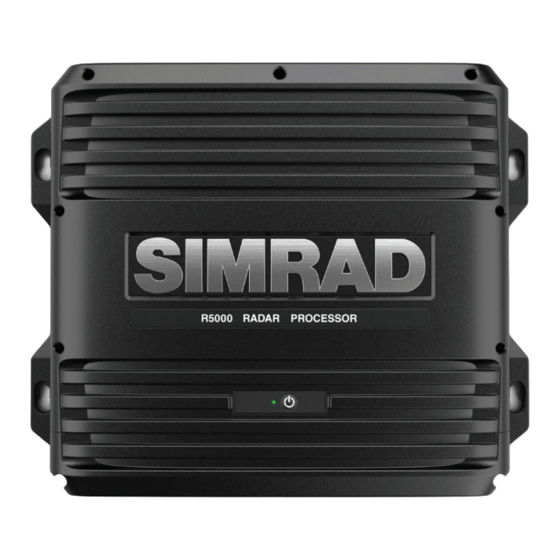
Simrad R5000 Installation Manual
Radar processor
Hide thumbs
Also See for R5000:
- Operator's manual (82 pages) ,
- Commissioning manual (49 pages) ,
- Installation manual (27 pages)
Table of Contents
Advertisement
Quick Links
Advertisement
Table of Contents

Summary of Contents for Simrad R5000
- Page 1 R5000 Radar processor Installation Manual ENGLISH www.navico.com/commercial...
- Page 3 Implementing Regulation (EU) 2018/773 (May 2018) - Wheelmark The relevant declaration of conformity is available in the product's section at the following website: • www.navico-commercial.com About this manual Intended audience This manual is written for system installers. Preface | R5000 radar processor Installation Manual...
- Page 4 Only reading these operating instructions cannot replace such training. Persons authorized to operate, maintain and troubleshoot the system are instructed and trained by Simrad. Persons operating or servicing this radar system must be familiar with the general safety regulations and specific safety systems, and they must have passed all required training.
- Page 5 Main power is always present on the terminal board unless the main break from the power distribution panel of the vessel is turned off. Warning: Never look down a waveguide from which power is being radiated! Preface | R5000 radar processor Installation Manual...
-
Page 6: Table Of Contents
Serial Alarm DGT (Dangerous Target) DMA (Dead Man Alarm) Monitor Ethernet NMEA 2000 Video in USB devices Card reader 17 Technical specifications R5000 processor unit 18 Accessories 19 Dimensional drawings R5000 processor unit Contents | R5000 radar processor Installation Manual... -
Page 7: Parts Included
1x serial (14 positions) • 1x serial (10 positions) • 3x alarm/DGT/DMA (2 positions) • Terminal connector kit Document pack DVI cable for monitor connection Serial cable for monitor control, with terminal plugs Parts included | R5000 radar processor Installation Manual... -
Page 8: Installation
Exposing the unit to conditions that exceed the specifications could invalidate your warranty, refer to the technical specification in the on page 17. "Technical specifications" Wall mounting Installation | R5000 radar processor Installation Manual... -
Page 9: Wiring
O2000 controller O2000 power supply unit R5000 control station Connectors R5000 radar processor unit NETWORK VIDEO IN SERIAL ALARM NMEA MONITOR MICRO POWER 2000 Ú Note: The video in connectors are not used. Wiring | R5000 radar processor Installation Manual... -
Page 10: Power
4 in port 4 in Geographic port 4 in port 4 in port 4 in position- latitude and longitude Global port 4 in port 4 in port 4 in positioning system (GPS) fix data Wiring | R5000 radar processor Installation Manual... - Page 11 6 out port 6 out Serial 1-2 Unit socket (male) Cable plug (female) Port Purpose Listener A (Rx_A) Listener B (Rx_B) Common Port 1 Ground (IEC 61162-2) Talker A (Tx_A) Talker B (Tx_B) Shield Wiring | R5000 radar processor Installation Manual...
- Page 12 Talker A (Tx_A) Talker B (Tx_B) Serial 5-6 Unit socket (male) Cable plug (female) Port Purpose Listener A (Rx_A) Listener B (Rx_B) Port 5 Shield (IEC 61162-1) Talker A (Tx_A) Talker B (Tx_B) Wiring | R5000 radar processor Installation Manual...
-
Page 13: Alarm
External alarm output normally closed, isolated contact DGT (Dangerous Target) The DGT output is active when a radar target or AIS target is classified as dangerous. DGT connector details Unit socket (male) Cable plug (female) Wiring | R5000 radar processor Installation Manual... -
Page 14: Dma (Dead Man Alarm)
The unit is equipped with standard DVI connector(s). The unit should be turned off prior to connecting or disconnecting a DVI cable. Monitor control wiring A serial connection to the monitor is required to control the monitor brightness. Wiring | R5000 radar processor Installation Manual... -
Page 15: Ethernet
The NEMA 2000 network is used to connect a remote controller to the unit. NMEA 2000 connector details Unit socket (male) Cable plug (female) Purpose Shield NET-S (+12 V DC) NET-C (DC negative) NET-H NET-L Video in Video in is not to be used. Wiring | R5000 radar processor Installation Manual... -
Page 16: Usb Devices
The unit is equipped with standard USB type-A connector(s). Card reader A memory card can be used for: • Software updates • Transfer of user data • System backup Card details The unit supports standard MicroSD cards. Wiring | R5000 radar processor Installation Manual... -
Page 17: Technical Specifications
AIS target is classified as dangerous DMA (Dead Man Alarm) DMA output, active when an action is made on the control panel Monitor DVI output to remote display Card reader 1 MicroSD card reader Technical specifications | R5000 radar processor Installation Manual... -
Page 18: Accessories
Accessories The most up-to-date accessories list is available at: • www.navico-commercial.com Accessories | R5000 radar processor Installation Manual... -
Page 19: Dimensional Drawings
Dimensional drawings R5000 processor unit 281 mm (11.05”) 265 mm 69 mm (10.42”) (2.73”) Dimensional drawings | R5000 radar processor Installation Manual... - Page 21 www.navico.com/commercial...


Need help?
Do you have a question about the R5000 and is the answer not in the manual?
Questions and answers