Table of Contents
Advertisement
Quick Links
Advertisement
Table of Contents

Related Manuals for Commell LV-651 series


Summary of Contents for Commell LV-651 series
- Page 1 LV-651 Mini-ITX Motherboard User’s Manual Edition 1.0 2006/7/21...
- Page 2 Trademark All trademarks are the property of their respective holders. Any questions please visit our website at h ttp://www.commell.com.tw...
- Page 3 LV-651User’s Manual Packing List Please check the package before you starting setup the system Hardware: LV-651 series motherboard x 1 Cable Kit: 40pin 44pin 44pin 44-pin ATA33 IDE Cable x 1 COM port Cable x1 I/O Shield Cable x 1...
- Page 4 LV-651User’s Manual Index Chapter 1 <Introduction> ..............7 1.1 <Product Overview> ................7 1.2 <Product Specification> .................8 1.3 <Mechanical Drawing> .................10 1.4 <Block Diagram>...................11 2.1 <Connector Location> ................12 2.3.1 <Internal Connector>..............14 2.3.2 <External Connector>..............14 2.4 <CPU and Memory Setup> ..............15 2.4.1 <CPU Setup>...
- Page 5 LV-651User’s Manual A.4 <CRT Port> ....................40 A.5 <LAN Port> ....................40 A.6 < USB Port >..................40 A.7 <PS/2 Keyboard & Mouse Port>............41 A.8 < LPT Port >...................41 Appendix B <Flash BIOS> ..............43 BIOS Auto Flash Tool ..............43 Flash Method ..................43 Appendix C <System Resources>...
- Page 6 LV-651User’s Manual (The Page is Left For Blank)
-
Page 7: Chapter 1
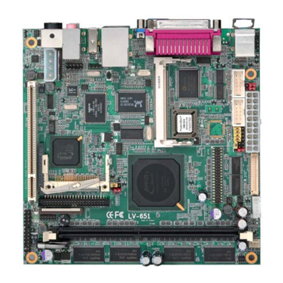
LV-651 User’s Manual Introduction Chapter 1 <Introduction> 1.1 <Product Overview> LV-651 is the Mini-ITX motherboard with AMD Geode LX800 platform, with onboard VGA, AC97 audio, Giga LAN interface. Based on the AMD Geode LX800 processor, the board provides many advanced features for reduced power consumption, fanless design and high cost/price rate of production. -
Page 8: Product Specification
LV-651 User’s Manual Introduction 1.2 <Product Specification> General Specification Form Factor Mini -ITX motherboard Embedded AMD Geode LX800 500MHz Fanless with heat sink only Memory One 184-pin DDR DIMM socket support up to 1GB DDR SDRAM Optional on board 256M DDR SDRAM Unbufferred, none-ECC memory supported only Chipset AMD LX800 and CS5536... - Page 9 LPT, RS232, USB2.0, Audio, IEEE1394, LCD and DDR DIMM LV651X-256 Same as above but with 256M DDR SDRAM on board The specifications may be different as the actual production. For further product information please visit the website at h ttp://www.commell.com.tw Product Specification...
-
Page 10: Mechanical Drawing
LV-651 User’s Manual Introduction 1.3 <Mechanical Drawing> Mechanical Drawing... -
Page 11: Block Diagram
LV-651 User’s Manual Introduction 1.4 <Block Diagram> 1 x 184-pin DDR DIMM VGA monitor Up to 1GB LX800 TFT/LVDS LCD PCI/33Mhz AC97 Audio CompactFlash&IDE IEEE1394 CS5536 4 x USB2.0 ports Arbitor IT8209 83627HG-AW 8110S-32 Floppy Mini PCI slot GPIO PCI slot IrDA LPT Port BIOS... -
Page 12: Connector Location
LV-651 User’s Manual Hardware Setup Chapter 2 <Hardware Setup> 2.1 <Connector Location> CN_DIO DIMM SYSFAN JFRNT CN_USB1 CN_INV CN_LCD CN_LVDS MINIPCI CN_COM1/2 DC_OUT CDIN CN_AUDIO AUDIO DC_IN CRT USB_RJ45 FIREWIRE Connector Location... - Page 13 LV-651 User’s Manual Hardware Setup 2.2 <Jumper Reference> Jumper Function JRTC CMOS Operating/Clear Setting JV1/2 Setting COM Port Voltage LCD Panel Voltage Setting JVLCD JCSEL1/2 COM2 RS-232/422/485 Mode Selection Select ATX or AT power on function JRTC JVLCD JCSEL1 JCSEL2 JV1/2 Jumper Reference...
-
Page 14: Internal Connector
LV-651 User’s Manual Hardware Setup 2.3 <Connector Reference> 2.3.1 <Internal Connector> Connector Function Remark DIMM 184 -pin DDR SDRAM DIMM slot Standard 44-pin primary IDE connector Slim 26-pin slim type floppy connector Slim 20-pin power supply connector Standard Compact Flash Type II socket Standard DC_OUT 4-pin power output connector... -
Page 15: Cpu And Memory Setup
LV-651 User’s Manual Hardware Setup 2.4 <CPU and Memory Setup> 2.4.1 <CPU Setup> The board integrates AMD Geode LX800 500MHz processor with special design for power appliance. It requires only 3.8W power consumption at most, and is totally designed for fanless system. 2.4.2 <Memory Setup>... - Page 16 LV-651 User’s Manual Hardware Setup 2.5 <CMOS Setup> The board’s data of CMOS can be setting in BIOS. If the board refuses to boot due to inappropriate CMOS settings, here is how to proceed to clear (reset) the CMOS to its default values.
-
Page 17: Enhanced Ide & Cf Interface
LV-651 User’s Manual Hardware Setup 2.6 <Enhanced IDE & CF Interface> The board has one Ultra DMA33 IDE interface to support up to 2 ATAPI devices, and one Compact Flash Type II socket on the solder side. Enhanced IDE & CF Interface... -
Page 18: Floppy Port
LV-651 User’s Manual Hardware Setup 2.7 <Floppy Port> The board provides a slim type floppy port; please use the 26-pin FPC cable in the package to connect the floppy device. Floppy rear side Lift up this plastic bar Slot the cable in (Blue paste for outside) Press back the plastic bar Lift up the brown plastic bar Slot the cable in (Blue paste for... -
Page 19: Lan Interface
LV-651 User’s Manual Hardware Setup 2.8 <LAN Interface> The board integrates with one Realtek RTL8110S-32 Gigabit Ethernet controller. The Realtek RTL8110S-32 supports triple speed of 10/100/1000Base-T, with IEEE802.3 compliance and Wake-On-LAN supported. USB_RJ45 2.9 <Onboard Display Interface> The board integrates AMD Geode LX800 processor with built-in 2D video engine, to provide onboard DB15 VGA connector, 24-bit TFT and 18-bit/24-bit LVDS interface. -
Page 20: Digital Display
LV-651 User’s Manual Hardware Setup 2.9.2 <Digital Display> The board provides one 40-pin LVDS connector for 18-bit single channel panel, supports up to 1024 x 768 of resolution, with one LCD backlight inverter connector and one jumper for panel voltage setting Connector: CN_INV Connector model: JST B5B-XH-A Connector: JVLCD... - Page 21 LV-651 User’s Manual Hardware Setup Connector: CN_LVDS ( for 24bit Single channel LVDS panel ) Type: 40-pin header (40 x 2 pitch 2.0 mm) Connector model: Hirose DF13- 40DP-1.25V Signal (18-bit) Signal (24-bit) LCDVCC LCDVCC TA2- TA2+ TB2- TB2+ TC2- TC2+ TD2- TD2+...
- Page 22 LV-651 User’s Manual Hardware Setup Connector: CN_LVDS ( for 18bit Single channel LVDS panel ) Type: 40-pin header (40 x 2 pitch 2.0 mm) Connector model: Hirose DF13-40DP-1.25V Signal (18-bit) Signal (24-bit) LCDVCC LCDVCC TA1- TA1+ TB1- TB1+ TC1- TC1+ TCLK1- TCLK1+ 18-bit single...
- Page 23 LV-651 User’s Manual Hardware Setup Connector: CN_LCD Type: onboard 2 x 20-pin header with housing, pitch=2.0mm Signal Signal ENAVDD ENAVEE VLCD VLCD GFP0 GFP1 GFP2 GFP3 GFP4 GFP5 GFP6 GFP7 GFP8 GFP9 GFP10 GFP11 GFP12 GFP13 GFP14 GFP15 GFP16 GFP17 GFP18 GFP19 GFP20...
- Page 24 LV-651 User’s Manual Hardware Setup To setup the LCD, you need the component below: A panel with LVDS interfaces. An inverter for panel’s backlight power. A LCD cable and an inverter cable. For the cables, please follow the pin assignment of the connector to make a cable, because every panel has its own pin assignment, so we do not provide a standard cable;...
- Page 25 LV-651 User’s Manual Hardware Setup After setup the devices well, you need to select the LCD panel type in the BIOS. The panel type mapping is list below: Panel Number Resolution 640 x 480 800 x 600 1024x 768 Digital Display...
-
Page 26: Onboard Audio Interface
LV-651 User’s Manual Hardware Setup 2.10 <Onboard Audio Interface> The board provides the onboard AC97 2 channel audio interface with Realtek ALC203. Connector: CN_AUDIO Type: 10-pin (2 x 5) 2.54mm x 2.54mm-pitch header Description Description LIN_L Ground LIN_R MIC 2 MIC 2 Ground FRONTL... -
Page 27: Usb2.0 Interface
LV-651 User’s Manual Hardware Setup 2.11 <USB2.0 Interface> Based on AMD CS5536, the board provides 2 x USB2.0 ports. The USB2.0 interface provides up to 480Mbps of transferring rate. Interface USB2.0 Controller CS5536 Transfer Rate Up to 480Mb/s Output Voltage 500mA CN_USB1 USB2.0 Interface... - Page 28 LV-651 User’s Manual Hardware Setup Connector: CN_USB Type: 10-pin (5 x 2) header for USB1/2 Ports Description Description Data0- Data1- Data0+ Data1+ Ground Ground Ground P.S : The USB2.0 will be only active when you connecting with the USB2.0 devices, if you insert an USB1.1 device, the port will be changed to USB1.1 protocol automatically.
-
Page 29: Gpio Interface
LV-651 User’s Manual Hardware Setup 2.12 <GPIO Interface> The board provides a programmable 8-bit digital I/O interface; you can use this general purpose I/O port for system control like POS or KIOSK. Connector: CN_DIO Type: onboard 2 x 6-pin header, pitch=2.0mm Description Description Ground... -
Page 30: Serial Port Jumper Setting
LV-651 User’s Manual Hardware Setup 2.13 <Serial Port Jumper Setting > The onboard CN_COM1 RS232 serial port, with jumper selectable RS232/422/485 for CN_COM2 Connector: COM1/2 Type: 9-pin Dip male connector on I/O Panel Description Description DCD/422RX-/485- RXD/422RX+/485+ TXD/422TX+ DTR/422TX- Jumper: JV1 Type: Onboard 3-pin jumper Mode COM1 pin-1 for +5V output... - Page 31 LV-651 User’s Manual Hardware Setup JCSEL1 JCSEL2 CN_COM1/2 JCSEL1 JCSEL2 RS-232 RS-485 RS-422 Serial Port Jumper Setting...
-
Page 32: Power Input
LV-651 User’s Manual Hardware Setup 2.14 <Power and Fan Connector> The LV-651 provides a standard ATX power supply with 20-pin ATX connector, and the board provides one 4-pin P4 additional use power connector for internal power supply and one 3-pin cooler fan connector for system . 2.14.1 <Power Input>... - Page 33 LV-651 User’s Manual Hardware Setup 2.14.3 <Fan Connector> Connector: SYSFAN Type: 3-pin fan wafer connector Description Description Description Ground +12V Fan Control Connector: DC_IN Type: 4-pin DC power connector Description Description +12V +12V Ground Ground SYSFAN DC_OUT DC_IN Power and Fan Connector...
- Page 34 LV-651 User’s Manual Hardware Setup 2.15 <Indicator and Switch> The JFRNT provides front control panel of the board, such as power button, reset and beeper, etc. Please check well before you connecting the cables on the chassis. Connector: JFRNT Type: onboard 14-pin (2 x 7) 2.54-pitch header Function Signal Signal...
- Page 35 LV-651 User’s Manual (This Page is Left For Blank...
-
Page 36: Chapter 3
LV-651 User’s Manual BIOS Setup Chapter 3 <BIOS Setup> The motherboard uses the Award BIOS for the system configuration. The Award BIOS in the single board computer is a customized version of the industrial standard BIOS for IBM PC AT-compatible computers. It supports Intel x86 and compatible CPU architecture based processors and computers. - Page 37 LV-651 User’s Manual (This Page is Left for Blank)
-
Page 38: Appendix A
LV-651 User’s Manual I/O Port Pin Assignment Appendix A <I/O Port Pin Assignment> A.1 <IDE Port> Connector: IDE1 Type: 44-pin (22 x 2) box header Description Description Reset Ground Ground Ground IOW-/STOP Ground IOR-/HDMARDY Ground IORDY/DDMARDY Ground DACK- Ground CS1- CS3- HD LED1- Ground... -
Page 39: A.2
LV-651 User’s Manual I/O Port Pin Assignment A.2 <Floppy Port> Connector: FDD Type: 26-pin connector Description Description INDEX DRV0 DSKCHG DRV1 MTR1 MTR0 STEP Ground WRITE DATA Ground WRITE GATE TRACK 0 WRPTR Ground RDATA- Ground A.3 <Serial Port> Connector: COM1/2 Type: 9-pin D-sub male connector on bracket Description Description... -
Page 40: A.4
LV-651 User’s Manual I/O Port Pin Assignment A.4 <CRT Port> Connector: CRT Type: 15-pin D-sub female connector on I/O Panel Description Description Description Ground GREEN Ground 5VCDA BLUE Ground HSYNC LVGA5V VSYNC Ground Ground 5VCLK A.5 <LAN Port> Connector: RJ45 Type: RJ45 connector with LED on I/O Panel Description MI0+... -
Page 41: A.7
LV-651 User’s Manual I/O Port Pin Assignment A.7 <PS/2 Keyboard & Mouse Port> Connector: Keyboard Type: 6-pin Mini-DIN connector on bracket Description KB_CK BVCC IOGND KB_DT Connector: Mouse Type: 6-pin Mini-DIN connector on bracket Description MS_CK BVCC IOGND MS_DT A.8 < LPT Port > Connector : LPT Type :25-Pin D-sub female Connector on bracket Description... - Page 42 LV-651 User’s Manual (This Page is Left for Blank)
-
Page 43: Appendix B
The board is based on Award BIOS and can be updated easily by the BIOS auto flash tool. You can download the tool online at the address below: h ttp://www.award.com h ttp://www.commell.com.tw/support/support.htm File name of the tool is “awdflash.exe”, it’s the utility that can write the data into the BIOS flash ship and update the BIOS. -
Page 44: Appendix C
LV-651 User’s Manual System Resources Appendix C <System Resources> C1.<I/O Port Address Map> I/O Port Address Map... - Page 45 LV-651 User’s Manual System Resources I/O Port Address Map...
- Page 46 LV-651 User’s Manual System Resources C2.<Memory Address Map> Memory Address Map...
- Page 47 LV-651 User’s Manual System Resources C3.<System IRQ Resources> System IRQ Resources...
- Page 48 LV-651 User’s Manual Programming GPIO’s Appendix D <Programming GPIO’s> The GPIO can be programmed with the MSDOS debug program using simple IN/OUT commands. The following lines show an example how to do this. GPIO0...GPIO7 bit0……bit7 -o 4E 87 ;enter configuration -o 4E 87 -o 4E 2A -o 4F FD...
- Page 49 LV-651 User’s Manual Watch Dog timer Setting Appendix E <Watch Dog timer Setting > The watchdog timer makes the system auto-reset while it stops to work for a period. The integrated watchdog timer can be setup as system reset mode by program. Timeout Value Range - 1 to 255 - Second or Minute...
- Page 50 LV-651 User’s Manual (This Page is Left for Blank)
-
Page 51: Contact Information
8F, No. 94, Sec. 1, Shin Tai Wu Rd., Shi Chih Taipei Hsien, Taiwan +886-2-26963909 +886-2-26963911 Website h ttp://www.commell.com.tw E-Mail i nfo@commell.com.tw (General Information) t ech@commell.com.tw (Technical Support) Commell is a brand name of Taiwan Commate Computer INC Contact Information...
Need help?
Do you have a question about the LV-651 series and is the answer not in the manual?
Questions and answers