Table of Contents
Advertisement
Quick Links
Advertisement
Table of Contents

Related Manuals for Commell LV-66A


Summary of Contents for Commell LV-66A
- Page 1 LV-66A Mini-ITX Motherboard User’s Manual Edition 1.02 2009/02/17...
- Page 2 LV-66A User’s Manual Copyright Copyright 2008. All rights reserved. This document is copyrighted and all rights are reserved. The information in this document is subject to change without prior notice to make improvements to the products. This document contains proprietary information and protected by copyright. No part of this document may be reproduced, copied, or translated in any form or any means without prior written permission of the manufacturer.
-
Page 3: Packing List
LV-66A User’s Manual Packing List Please check the package before you starting setup the system Hardware: LV-66A series motherboard x 1 Cable Kit: 40-pin ATA100 IDE Cable x 1 44-pin ATA33 IDE Cable x 1 26-pin Slim Type Floppy Cable x 1 Printer Port Cable &... - Page 4 LV-66A User’s Manual Index Chapter 1 <Introduction> ..............7 1.1 <Product Overview>................. 7 1.2 <Product Specification> ................8 1.3 <Mechanical Drawing>................10 1.4 <Block Diagram>..................11 Chapter 2 <Hardware Setup> ............12 2.1 <Connector Location>................12 2.2 <Jumper Reference> ................14 2.3 <Connector Reference>.................
- Page 5 LV-66A User’s Manual 2.14 <Serial Port Jumper Setting > .............. 32 2.15 <Fan Connector> ................. 34 2.16 <Indicator and Switch>................. 35 2.17 <Power Supply>................... 36 2.17.1 <DC_IN Input>................36 2.17.2 <ATX Input> ................37 Chapter 3 <System Configuration> ........... 39 3.1 <SATA RAID Configuration>..............
- Page 6 LV-66A User’s Manual (The Page is Left For Blank)
-
Page 7: Chapter 1
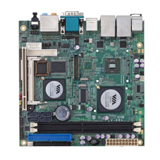
Chapter 1 <Introduction> 1.1 <Product Overview> LV-66A is the Mini-ITX motherboard based on VIA chipset. It integrates VIA embedded chipset for CN896 with VT8251, two DDR2 400/533/667 SDRAM 64-bit single channel, and serial ATA II supporting 1.5 Gbit/s and 3 Gbit/s transfer rate with RAID 0/1/0+1/5 and JBOD array Technology supported to provide the economical embedded platform. -
Page 8: Product Specification
LV-66A User’s Manual Introduction 1.2 <Product Specification> General Specification Form Factor Mini-ITX motherboard VIA C7 1.5GHz processor L1/L2 Cache: 64 KB/128KB Front side bus: 400MHz 400/533/667 Memory 2 x 240-pin DDR2 SDRAM up to 4GB Advanced 64-bit single channel, Unbufferred, non-ECC memory supported only... - Page 9 LV-66A User’s Manual Hardware Setup Connector External DB15 female VGA connector on rear I/O panel Onboard 40-Pin LVDS connector(LV-66AX series only) Onboard 26-Pin DVI connector(LV-66AD series only) Ethernet Interface Chipset REALTEK RTL8111C Type Integrated 10/100/1000 transceiver auto-switching Fast Ethernet Full Duplex flow control (IEEE 802.3x), Fully compliant with IEEE 802.3, IEEE 802.3u, IEEE 802.3ab...
-
Page 10: Mechanical Drawing
LV-66A User’s Manual Introduction 1.3 <Mechanical Drawing>... -
Page 11: Block Diagram
LV-66A User’s Manual Hardware Setup 1.4 <Block Diagram> C7 VIA nanoBGA2 CRT/LCD Monitor CN896 VT1636 LVDS/VT1632A DVI 2 x 240-pin DDR2 400/533/667 Up to 4GB Ultra V-Link 533MB/s 8 x USB2.0 Ports 4 x SATA HD ALC888 VT8251 40-Pin 44-Pin IDE... -
Page 12: Chapter 2
LV-66A User’s Manual Hardware Setup Chapter 2 <Hardware Setup> 2.1 <Connector Location> SATA2/4 SATA1/3 IDE1 IDE2 SYSFAN JFRNT DDRIIB DDRIIA CN_FUSB CN_IR JRTC CPUFAN CN_DVI/ CN_LVDS MINIPCI CN_DIO CN_LPT CN_COM2 JCSEL2 JCSEL1 CN_FAUDIO CN_CRT CDIN USB-RJ45_2 AUDIO SPDIF CRT+COM USB-RJ45_1... - Page 13 LV-66A User’s Manual Hardware Setup CRT+COM AUDIO SPDIF CDIN USB_RJ45_1/2 170mm 170mm 14.25’...
-
Page 14: Jumper Reference
LV-66A User’s Manual Hardware Setup 2.2 <Jumper Reference> Jumper Function JRTC CMOS Operating/Clear Setting JVLCD LCD Panel Voltage Setting (LV-66AX series only) AT/ATX mode setting JCSEL1/2 CN_COM2 RS232/422/485 mode setting JRTC JCSEL2 JCSEL1 JVLCD... -
Page 15: Connector Reference
LV-66A User’s Manual Hardware Setup 2.3 <Connector Reference> 2.3.1 <Internal Connector> Connector Function Remark DDRIIA&DDRIIB 240-pin DDR2 SDRAM DIMM Standard IDE1 40-pin primary IDE connector Standard IDE2 44-pin secondary IDE connector Slim 26-pin slim type floppy connector Slim SATA1/2/3/4 7-pin Serial ATA connector... -
Page 16: Cpu And Memory Setup
LV-66A User’s Manual Hardware Setup 2.4 <CPU and Memory Setup> 2.4.1<CPU> The board supports VIA C7 processor, default ratio is C7 1.5G 12W with cooler. 2.4.2 <Memory> The board supports two 240-pin DDR2 400/533/667 SDRAM and up to 4GB Advanced 64-bit single channel, of capacity, only non-ECC, unbuffered memory is supported. -
Page 17: Cmos & At/Atx Setup
LV-66A User’s Manual Hardware Setup 2.5 <CMOS & AT/ATX Setup> The board’s data of CMOS can be setting in BIOS. If the board refuses to boot due to inappropriate CMOS settings, here is how to proceed to clear (reset) the CMOS to its default values. -
Page 18: Solid State Disk Interface
LV-66A User’s Manual Hardware Setup 2.6 <Solid State Disk Interface> The board has one Compact Flash Type II socket on the solder side, with jumper JCFSEL for CF master/slave mode selection. (Optional) Jumper: JCFSEL Type: Onboard 3-pin jumper JCFSEL Mode... -
Page 19: Serial Ata Interface
LV-66A User’s Manual Hardware Setup 2.7 <Serial ATA Interface> Based on VIA VT8251 Southbridge, the board supports four Serial ATA interfaces with RAID array function. The following is the list of the specification of the Serial ATA. Complies with Serial ATA Specification Revision 1.0 Complies with Serial ATA II Specification. -
Page 20: Floppy Port
LV-66A User’s Manual Hardware Setup 2.8 <Floppy Port> The board provides a slim type floppy port; please use the 26-pin ribbon cable in the package to connect the floppy device. Floppy rear side Lift up this plastic bar Slot the cable in (Blue paste for outside) -
Page 21: Lan Interface
LV-66A User’s Manual Hardware Setup 2.9 <LAN Interface> The board provides two REALTEK RTL8111C GigaLAN interfaces and compliant. Standard Integrated 10/100/1000 transceiver, auto-switching Fast Ethernet, Full Duplex flow control (IEEE 802.3x), Fully compliant with IEEE 802.3, IEEE 802.3u, IEEE 802.3ab. -
Page 22: Onboard Display Interface
LV-66A User’s Manual Hardware Setup 2.10 <Onboard Display Interface> Based on VIA CN896, the board supports Chrome9™ HC Integrated Graphics with 2D / 3D / Video Controllers, with BIOS selectable 64/128/256MB shared with system memory for frame buffer. 2.10.1 <Analog VGA Interface>... -
Page 23: Digital Display
LV-66A User’s Manual Hardware Setup 2.10.2 <Digital Display> 2.10.2.1 <LVDS Display> The board provides one 40-pin LVDS connector for single/dual 18/24-bit channel panels, supports up to 1920 x 1200 of resolution, with one LCD backlight inverter connector and one jumper for panel voltage setting (LV-66AX series only) - Page 24 LV-66A User’s Manual Hardware Setup Connector: CN_INV Connector: JVLCD Type: 5-pin LVDS Power Header Type: 6-pin Power select Header Connector model: JST B5B-XH-A Description Description +12V LCDVCC (+3.3V) LCDVCC (+5V) LCDVCC (+12V) Default setting: 1-2 ENABKL Connector: CN_LVDS Type: onboard 40-pin connector for LVDS connector Connector model: HIROSE DF13-40DP-1.25V...
- Page 25 LV-66A User’s Manual Hardware Setup To setup the LCD, you need the component below: A panel with LVDS interfaces. An inverter for panel’s backlight power. A LCD cable and an inverter cable. For the cables, please follow the pin assignment of the connector to make a cable, because every panel has its own pin assignment, so we do not provide a standard cable;...
- Page 26 LV-66A User’s Manual Hardware Setup After setup the devices well, you need to select the LCD panel type in the BIOS. The panel type mapping is list below: LV-66AX BIOS panel type selection form VGA ROM VERSION: Resolution Color Channel...
-
Page 27: Dvi Display
LV-66A User’s Manual Hardware Setup 2.10.2.2 <DVI Display> The board provides one 26-pin DVI connector, supports up to 1600 x 1200 of resolution. (LV-66AD series only) Connector: CN_DVI Type: onboard 26-pin connector for DVI connector Type: onboard 2 x 13-pin box header, pitch=2.0mm... -
Page 28: Onboard Audio Interface
LV-66A User’s Manual Hardware Setup 2.11 <Onboard Audio Interface> The board provides Realteck ALC888 7.1-channel HD audio interface. Connector: CN_FAUDIO Type: 10-pin (2 x 5) header (pitch = 2.54mm) Description Description MIC2_L Ground MIC2_R AVCC (3.3V) FP_OUT_R MIC2_JD SENSE FP_OUT_L... -
Page 29: Usb2.0 Interface
LV-66A User’s Manual Hardware Setup 2.12 <USB2.0 Interface> Based on VIA VT8251, the board provides eight USB2.0 ports. The USB2.0 interface provides up to 480Mbps of transferring rate. Interface USB2.0 Controller VIA VT8251 Transfer Rate Up to 480Mb/s Output Current... - Page 30 LV-66A User’s Manual Hardware Setup Connector: CN_FUSB Type: 10-pin (5 x 2) header, pitch=2.54mm Description Description VCC (5V) VCC (5V) Data0- Data1- Data0+ Data1+ Ground Ground Ground PS: The USB2.0 will be only active when you connecting with the USB2.0 devices, if you insert an USB1.1 device, the port will be changed to USB1.1 protocol automatically.
-
Page 31: Gpio Interface
LV-66A User’s Manual Hardware Setup 2.13 <GPIO Interface> The board provides a programmable 8-bit digital I/O interface; you can use this general purpose I/O port for system control like POS or KIOSK. Connector: CN_DIO Type: onboard 2 x 6-pin header, pitch=2.0mm... -
Page 32: Serial Port Jumper Setting
LV-66A User’s Manual Hardware Setup 2.14 <Serial Port Jumper Setting > The board provides three RS232 serial ports, with jumper selectable RS422/485 for CN_COM2. Connector: CN_COM2 Type: 10-pin (5 x 2) header, pitch=2.54mm Description Description DCD/422TX-/485- RXD/422TX+/485+ TXD/422RX+ DTR/422RX- JCSEL1... - Page 33 LV-66A User’s Manual Hardware Setup CN_COM2 JCSEL1 JCSEL2...
-
Page 34: Fan Connector
LV-66A User’s Manual Hardware Setup 2.15 <Fan Connector> Connector: CPUFAN, SYSFAN Type: 3-pin fan wafer connector Description Description Description Ground +12V Fan Control SYSFAN CPUFAN... -
Page 35: Indicator And Switch
2.16 <Indicator and Switch> The JFRNT provides front control panel of the board, such as power button, reset and beeper, etc. Please check well before you connecting the cables on the chassis. Connector: JFRNT Type: onboard 14-pin (2 x 7) 2.54-pitch header Function Signal Signal... -
Page 36: Power Supply
LV-66A User’s Manual Hardware Setup 2.17 <Power Supply> The board requires onboard 4-pin DC-input connector voltage is 12V, or onboard 20-pin ATX2.0, for the input current, please take a reference of the power consumption report on. 2.17.1 <DC_IN Input> Connector: DC_IN... -
Page 37: Atx Input
LV-66A User’s Manual Hardware Setup 2.17.2 <ATX Input> Connector: ATX (It also can become Output) Type: 20-pin ATX power connector PIN assignment 3.3V 3.3V 3.3V -12V -PSON PW_OK 5V_SB... - Page 38 LV-66A User’s Manual (This Page is Left For Blank)
-
Page 39: Chapter 3
LV-66A User’s Manual System Configuration Chapter 3 <System Configuration> 3.1 <SATA RAID Configuration> The board supports four Serial ATA ports onboard, and supports RAID 0, 1, 0+1, 5 and JBOD disk array, the RAID 0, 1, 0+1, 5 and JBOD are specified below:... - Page 40 LV-66A User’s Manual JBOD (Span): Span Array is also called JBOD (Just a Bunch Of Disks), which uses a bunch of disks as a larger disk. Span provides no fault tolerance and no I/O performance enhancement, it's just a measure to enlarge disk capacity.
- Page 41 LV-66A User’s Manual System Configuration You also can edit disk array under OS, please install the VIA RAID Utility in the driver CD. (To getting start, please click here to learn more information) The RAID Mode block will list all available RAID type according to the number of available free-disk.
-
Page 42: Audio Configuration
LV-66A User’s Manual System Configuration 3.2 <Audio Configuration> The board provides 7.1 channel HD audio interface with driver installed, please install the Realtek ALC888 HD audio driver in the CD before getting start to enjoy the 7.1 channel sound system. -
Page 43: Display Configuration
LV-66A User’s Manual System Configuration 3.3 <Display Configuration> The board provides onboard analog VGA interface, and optional digital display interface with LVDS or DVI, please install the VIA video driver before enjoy the vivid display. Based on the VIA CN896 with Chrome9™ HC Integrated Graphics, the board provides dual display function for clone or extended desktop modes with secondary display device attached. - Page 44 LV-66A User’s Manual System Configuration Two controllers for each display device There are two options for secondary display device For more display properties setting, please click “Advanced” button.
- Page 45 LV-66A User’s Manual System Configuration Please select S3Display for advanced device setting. Connected Devices Click check box to enable/disable device Specified display setup if available Set dual display clone mode and extended desktop mode When you set dual display clone mode, you’ll see the same screen display on two devices.
- Page 46 LV-66A User’s Manual System Configuration (This Page is Left for Blank)
-
Page 47: Chapter 4
LV-66A User’s Manual Chapter 4 <BIOS Setup> The motherboard uses the Award BIOS for the system configuration. The Award BIOS in the single board computer is a customized version of the industrial standard BIOS for IBM PC AT-compatible computers. It supports Intel x86 and compatible CPU architecture based processors and computers. - Page 48 LV-66A User’s Manual I/O Port Pin Assignment (This Page is Left for Blank)
-
Page 49: Appendix A
LV-66A User’s Manual I/O Port Pin Assignment Appendix A <I/O Port Pin Assignment> A.1 <IDE Port> Connector: IDE1 Type: 40-pin (20 x 2) box header Description Description Reset Ground Ground Ground IOW-/STOP Ground IOR-/HDMARDY Ground IORDY/DDMARDY IDESEL DACK- Ground CBLID... - Page 50 LV-66A User’s Manual I/O Port Pin Assignment Connector: IDE2 Type: 44-pin (22 x 2) box header Description Description Reset Ground Ground Ground IOW-/STOP Ground IOR-/HDMARDY Ground IORDY/DDMARDY Ground DACK- Ground ASP1 Ground Ground Ground...
-
Page 51: A.2
LV-66A User’s Manual I/O Port Pin Assignment A.2 <Floppy Port> Connector: FDD Type: 26-pin connector Description Description INDEX DRV0 DSKCHG DRV1 MTR1 MTR0 STEP Ground WRITE DATA Ground WRITE GATE TRACK 0 WRPTR Ground RDATA- Ground A.3 <Serial ATA Port>... -
Page 52: A.4 < Crt Port
LV-66A User’s Manual I/O Port Pin Assignment A.4 < CRT Port > Connector: VGA Type: 15-pin D-sub female connector on panel Description Description Description Ground GREEN Ground 5VCDA BLUE Ground HSYNC LVGA5V VSYNC Ground Ground 5VCLK A.5 <Serial Port> Connector: COM... -
Page 53: Appendix B
LV-66A User’s Manual Flash BIOS Appendix B <Flash BIOS> B.1 BIOS Auto Flash Tool The board is based on Award BIOS and can be updated easily by the BIOS auto flash tool. You can download the tool online at the address below: http://www.award.com.tw/... -
Page 54: Appendix C
LV-66A User’s Manual System Resources Appendix C <System Resources> C1.<I/O Port Address Map>... - Page 55 LV-66A User’s Manual System Resources...
-
Page 56: C2.
LV-66A User’s Manual System Resources C2.<Memory Address Map>... - Page 57 LV-66A User’s Manual System Resources...
-
Page 58: C3.
LV-66A User’s Manual System Resources C3.<System IRQ Resources>... -
Page 59: Appendix D
LV-66A User’s Manual Programming GPIO’s Appendix D <Programming GPIO’s> The GPIO can be programmed with the MSDOS debug program using simple IN/OUT commands. The following lines show an example how to do this. GPIO0...GPIO7 bit0……bit7 -o 2E 87 -o 2E 87 ;enter configuration... - Page 60 LV-66A User’s Manual Programming GPIO’s datasheet.
-
Page 61: Appendix E
LV-66A User’s Manual Programming GPIO’s Appendix E <Watch Dog timer Setting > The watchdog timer makes the system auto-reset while it stops to work for a period. The integrated watchdog timer can be setup as system reset mode by program. - Page 62 LV-66A User’s Manual (This Page is Left for Blank)
-
Page 63: Contact Information
Taiwan Commate Computer Inc. Address 19F, No. 94, Sec. 1, Shin Tai Wu Rd., Shi Chih Taipei Hsien, Taiwan +886-2-26963909 +886-2-26963911 Website h ttp://www.commell.com.tw E-Mail i nfo@commell.com.tw (General Information) t ech@commell.com.tw (Technical Support) Commell is our trademark of industrial PC division...
Need help?
Do you have a question about the LV-66A and is the answer not in the manual?
Questions and answers