Table of Contents
Advertisement
Quick Links
Advertisement
Table of Contents

Related Manuals for Commell LV-6715


Summary of Contents for Commell LV-6715
- Page 1 LV-6715 Mini-ITX Mobile Motherboard User’s Manual Edition 1.1 2022/10/11...
- Page 2 LV-6715 User’s Manual Copyright Copyright 2022, all rights reserved. This document is copyrighted and all rights are reserved. The information in this document is subject to change without prior notice to make improvements to the products. This document contains proprietary information and protected by copyright. No part of this document may be reproduced, copied, or translated in any form or any means without prior written permission of the manufacturer.
- Page 3 LV-6715 User’s Manual Packing List: Please check the package content before you starting using the board. 1 x I/O Shield 1 x LV-6715 Mini-ITX Motherboard (OPLATE-CUHDLAT) / (1270077) (include Cooler Fan) 1 x DC Power Cable 1 x Adapter LAN Cable...
-
Page 4: Table Of Contents
LV-6715 User’s Manual Index Chapter 1 <Introduction>............... 4 1.1 <Product Overview>............4 1.2 <Product Specification> ............5 1.3 <Block Diagram>..............6 Chapter 2 <Hardware setup>............7 2.1 <Connector Location and Reference> ........ 7 2.1.1 <Internal connectors list> ..........8 2.1.2 <External connectors list>.........8 2.2 <Memory Setup>..............9... -
Page 5: Chapter 1
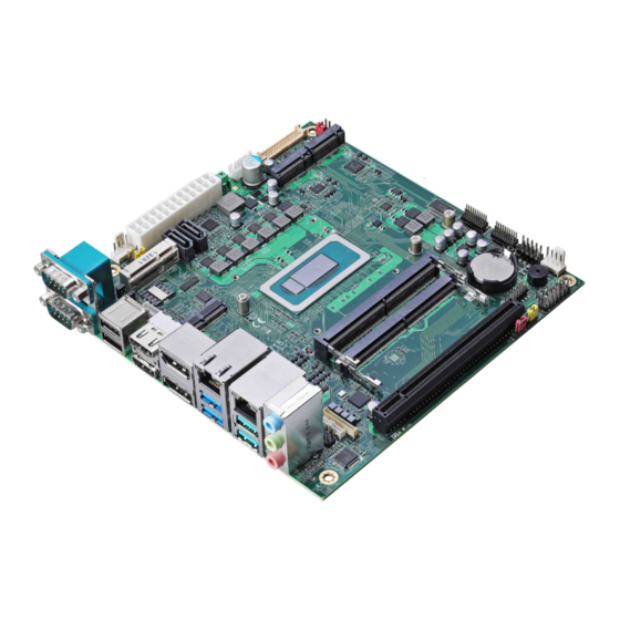
LV-6715 User’s Manual Chapter 1 <Introduction> 1.1 <Product Overview> LV-6715 is a Mini-ITX Motherboard which supports Alder Lake/12th Gen Processors, integrated DDR5 memory, Realtek High Definition Audio, Intel Gigabit LAN, USB3.2 Gen2, SATA3 with AHCI function for a system. New feature for Alder Lake Alder Lake/12th Gen Processors are based on the 7nm SuperFin process, and offer long-life availability. -
Page 6: Product Specification
LV-6715 User’s Manual 1.2 <Product Specification> System Intel® Alder Lake H Processor Processor FCBGA1744 package 2 x DDR5 SO-DIMM 4800 MHz up to 64GB, Memory Support Non-ECC, unbuffered memory Generates a system reset with internal timer for 1min/s ~ 255min/s... -
Page 7: Block Diagram
LV-6715 User’s Manual 1.3 <Block Diagram> PTN3460 DDR5 SODIMM 4800 DDR5 SODIMM 4800 LVDS 2 x M.2 KEY M 2280 1 x PCIe X16 Slot Alder Lake H Gen4 8x HDMI Processor HDMI DVI / HDMI I219-LM 1 x M.2 2230... -
Page 8: Chapter 2
LV-6715 User’s Manual Chapter 2 <Hardware setup> 2.1 <Connector Location and Reference> CN_COM3/4 CN_COM5/6 CN_USB SYSFAN M.2 HM CN_LVDS CN_DIO M.2 HM1 CN_INV DC_IN PCI_E16X SATA1 SATA2 MPX-H CN_SMBUS M.2 HE MINI_C CPUFAN CN_LAN3 JLANLED2 JLANLED1 CN_DVI/HDMI CN_ AUDIO COM2... -
Page 9: Internal Connectors List
LV-6715 User’s Manual 2.1.1 <Internal connectors list> Connector Function DDR5_A/B 262-pin DDR5 SO-DIMM slot SATA1/2 7-pin SATA3 connector CN_AUDIO 5 x 2-pin audio pin header CN_LVDS 20 x 2-pin LVDS connector CN_INV 5-pin LCD inverter connector CN_SMBUS 3-pin SMBus connector... -
Page 10: Memory Setup
LV-6715 User’s Manual 2.2 <Memory Setup> In the process, the board must be powered off. 1. Put the memory tilt into the slot. Note the Memory notch key aligned slot key. 2. Then press down till lock into the mounting notch. -
Page 11: Jumper Location And Reference
LV-6715 User’s Manual 2.3 <Jumper Location and Reference> JVLCD JRTC 2.3.1 <Jumper list> Jumper Function Power mode select JRTC CMOS Normal/Clear Setting JVLCD Panel Voltage Setting JMSATA MiniCard mSATA Setting COM1 Voltage Setting (For Pin 9) COM2 Voltage Setting (For Pin 9) -
Page 12: Clear Cmos And Power On Type Selection
LV-6715 User’s Manual 2.3.2 <Clear CMOS and Power on type selection> The board’s data of CMOS can be setting in BIOS. If the board refuses to boot due to inappropriate CMOS settings, here is how to proceed to clear (reset) the CMOS to its default values. -
Page 13: Ethernet Interface
LV-6715 User’s Manual 2.4.2 <Ethernet interface> The board provides I219-LM Gigabit Ethernet which supports WOL on rear I/O. It supports Intel® AMT 16.0 feature on I219-LM. (Note that the CPU must support vPro technology.) I226-LM I219-LM CN_LAN3 JLANLED1 (I219) CN_LAN3... -
Page 14: Display Interface
LV-6715 User’s Manual 2.4.3 <Display interface> Based on the 12th Gen CPU with built-in Intel® Iris® Xe Graphics, the DisplayPort resolution up to 3840x2160 @ 60Hz or 4096x2304 @ 60Hz, the HDMI up to 4096x2304 @ 24Hz and LVDS up to 1920x1200 @ 60Hz supports single bus or dual bus LVDS signaling with color depths of 18 bits or 24 bits. - Page 15 LV-6715 User’s Manual CN_LVDS: LVDS 40-pin connector ( Model: HIROSE DF13-40DP-1.25V compatible Signal Signal Set by JVLCD Set by JVLCD Detect (Active low) A_LVDS_0- B_LVDS_0- A_LVDS_0+ B_LVDS_0+ A_LVDS_1- B_LVDS_1- A_LVDS_1+ B_LVDS_1+ A_LVDS_2- B_LVDS_2- A_LVDS_2+ B_LVDS_2+ A_LVDS_CLK- B_LVDS_3- A_LVDS_CLK+ B_LVDS_3+ A_LVDS_3-...
-
Page 16: Serial Port Interface
LV-6715 User’s Manual 2.4.4 <Serial Port interface> COM2 COM1 COM1: RS232/422/485 DB9 connector Signal Signal DCD/ 422TX-/ 485- RXD/ 422TX+/ 485+ DSR/ 422RX+ CTS/ 422RX- Set by JP1 COM2: RS232/422/485 DB9 connector Signal Signal DCD/ 422TX-/ 485- RXD/ 422TX+/ 485+... - Page 17 LV-6715 User’s Manual COM1 & COM2 RS-232/422/485 can set by BIOS. You can find the setting from Advanced-> Motherboard Advanced menu-> Super IO configuration-> Serial Port configuration->Interface If you want to use RS485, please follow below step before connection. .
-
Page 18: Usb Interface
LV-6715 User’s Manual 2.4.5 <USB interface> USB2 USB3.2 Gen2 CN_USB CN_USB: USB2.0 10-pin header (Pitch 2.54 mm) Signal Signal 5VSB 5VSB DATA0- DATA1- DATA0+ DATA1+ -17-... -
Page 19: Audio Interface
LV-6715 User’s Manual 2.4.6 <Audio interface> Rear Audio Jack Line in Line out CN_AUDIO Mic in CN_AUDIO: Front panel audio 10-pin header (Pitch 2.54mm) Signal Signal MIC_L MIC_R FP_OUT_R MIC_DETECT SENSE FP_OUT_L FP_OUT_DETECT -18-... -
Page 20: Expansion Slot
LV-6715 User’s Manual 2.4.7 <Expansion slot> M.2 HM M.2 HM1 PCIE_16X MPX-H M.2 HE MINI_C JMSATA JMSATA: Setting MINI_CARD to support PCIe/MSATA MINI_CARD support mSATA by JMSATA, and connect SIM card M.2 HE with 2 x PCI Express x1 support WI-FI and Bluetooth Module... -
Page 21: Front Panel Switch And Indicator
LV-6715 User’s Manual 2.4.8 <Front panel switch and indicator> JFRNT JFRNT: Front panel switch and indicator 14-pin header (Pitch 2.54mm) Signal Signal HDD_LED+ Power_LED+ HDD_LED- Reset+ Power_LED- Reset- Speaker+ Power_ON+ Power_ON- Speaker- -20-... -
Page 22: Gpio And Other Interface
LV-6715 User’s Manual 2.4.9 <GPIO and Other interface> SYSFAN CN_DIO CN_SMBUS CPUFAN -21-... - Page 23 LV-6715 User’s Manual When using GPIO function, please note: As Output: Open-drain, most applications need use an external pull up resistor. (If not may cause damage) As Input: TTL-level. GPIO DC characteristics (open drain mode) Parameter UNIT Conditions Input Low Voltage...
-
Page 24: Power Supply
LV-6715 User’s Manual 2.5 <Power supply> 2.5.1 <Power input> DC_IN DC_IN: 2-pin 9~35V connector Signal Signal 9~35V ATX: main power 24-pin connector (DC_IN and ATX can’t use at the same time) Signal Signal 3.3V 3.3V 3.3V -PSON Power_OK 5VSB 3.3V... -
Page 25: Power Output
LV-6715 User’s Manual 2.5.2 <Power Output> It is supply to the HDD, CD-ROM or other device. If using DC_IN as input, that ATX will be the output. ATX: main power 24-pin connector (As output) Signal Signal 3.3V 3.3V 3.3V 3.3V... -
Page 26: Appendix A
LV-6715 User’s Manual Appendix A <Flash BIOS> A.1 <Flash tool> The board is based on Phoenix BIOS and can be updated easily by the BIOS auto flash tool. You can download the tool online at the address below: FPT Tool The tool’s file name is “FPT.exe”, it’s the utility that can write the data into the... -
Page 27: Appendix B
LV-6715 User’s Manual Appendix B <LCD Panel Type select> According your panel, it needs to select the correct resolution in the BIOS. If there is no fit your panel type, please feedback for us to make OEM model. Find the setting from Advanced->Motherboard Advanced menu->LVDS Configuration... -
Page 28: Appendix C
LV-6715 User’s Manual Appendix C <Programmable Watch Dog Timer> The watchdog timer makes the system auto-reset while it stops to work for a period. The integrated watchdog timer can be setup as system reset mode by program. You can select Timer setting in the BIOS, after setting the time options, the system will reset according to the period of your selection. - Page 29 LV-6715 User’s Manual Program sample Watchdog timer setup as system reset with 5 second of timeout -o 4E 87 ;enter configuration -o 4E 87 -o 4E 07 -o 4F 08 ;select Logical Device -o 4E 30 -o 4F 01 ; activate WDTO# function...
-
Page 30: Appendix D
LV-6715 User’s Manual Appendix D <Hardware Monitor> Find the setting from Advanced-> Motherboard Advanced menu-> Super IO configuration-> Hardware Monitor -29-... -
Page 31: Appendix E
LV-6715 User’s Manual Appendix E <Programmable GPIO> The GPIO can be programmed with the MS-DOS debug program using simple IN/OUT commands. GPIO -o 4E 87 ;enter configuration -o 4E 87 -o 4E 07 -o 4F 07 ;select Logical Device -o 4E 30 -o 4F 10 ;activate GPIO function (The board use GPIO4) -
Page 32: Appendix F
LV-6715 User’s Manual Appendix F <RAID Setting> When use RAID function, it need to enter the BIOS set RAID mode first. Advanced Intel Advanced menu SA Configuration VMD Configuraion 1. Find VMD controller, and set to enable 2. Set “Map this Root port under VMD” to enable. -
Page 33: Contact Information
Taiwan Commate computer Inc. 19F., NO.94, Sec. 1, Xintai 5 Rd., Xizhi Dist., New Taipei Address City 22102, Taiwan. +886-2-26963909 Website www.commell.com.tw info@commell.com.tw (General infomation) E-mail tech@commell.com.tw (Technical Support) Commell is a brand name of Taiwan Commate computer Inc. -32-...
Need help?
Do you have a question about the LV-6715 and is the answer not in the manual?
Questions and answers