Table of Contents
Advertisement
Quick Links
Cat. No. 01016449
Rev. B 03/04/14
DCO # 014223
Operating and
Instructions
CULLIGAN
CSM SERIES
®
C
F
ommercial
ilters
©2014 Culligan International Com pa ny
Printed in USA
Advertisement
Table of Contents

Related Manuals for Culligan CSM Series


Summary of Contents for Culligan CSM Series
- Page 1 Cat. No. 01016449 Rev. B 03/04/14 DCO # 014223 Installation, Operating and Service Instructions CULLIGAN CSM SERIES ® ommercial ilters ©2014 Culligan International Com pa ny Printed in USA...
- Page 2 Products manufactured and marketed by Culligan International Company (Culligan) and its affiliates are protected by patents issued or pending in the United States and other countries. Culligan reserves the right to change the specifications referred to in this literature at any time without prior notice. Culligan, Aqua-Sensor, Tripl-Hull, and SoftMinder are trademarks of Culligan International Company or its affiliates.
-
Page 3: Table Of Contents
Installation, Operating and Service Instructions CULLIGAN CSM SERIES ® ommercial ilters Contents Introduction ................ Appendix A Flow Device K-Factor Data ....... Performance Specifications ..........Appendix B Separate Source Assembly ...... Basic Principles ..............Program Log ..............Flow Diagram ..............Controller Features ............ - Page 4 This page intentionally left blank. Cat. No. 01016449 Culligan® CSM Series Filters...
-
Page 5: Introduction
Introduction Read this Manual First Before you operate the Culligan CSM Water Filter, read this manual to become familiar with the device and its capabilities. The Culligan CSM Water Filters are tested and certified by WQA against NSF/ANSI 372 for low lead requirement. -
Page 6: Performance Specifications
Loss Rate Loss Rate Loss LxWxH (gpm) (psi) (gpm) (psi) (gpm) (psi) (inches) 24 x 54 CSM-242R 25x33x74 30 x 60 CSM-302R 31x40x90 36 x 60 CSM-362R 37x46x90 42 x 60 CSM-422R 43x53x92 Cat. No. 01016449 Culligan® CSM Series Filters... - Page 7 Table 2. Specifications Table for Depth Commercial Water Filters Model Water Quality Backwash Media Tank Face Flow Size & Floor Piping Superior High Utility Rate Space Size Flow Pressure Flow Pressure Flow Pressure (gpm) Required (inches) Rate Loss Rate Loss Rate Loss LxWxH...
-
Page 8: Basic Principles
A depth filter should be cleaned when the differential pressure across the filter increases by 8-10 psi over the pressure differential across a clean filter bed. Cat. No. 01016449 Culligan® CSM Series Filters... -
Page 9: Flow Diagram
Flow Diagram Flow Diagram - SERVICE Service Step (H Position) These diagrams illus- trate the simplicity of the Brunermatic valve and positive control of flow direction. Note that only dia- phragm valves 1 & 4 are open and flow is directed to the top of Position media tank, through... -
Page 10: Figure
Note that only two valves Position Dial are open in this cycle (No. 6 and No. 17*). Pressure directed through pilot valve holds other valves closed. *Single tank systems requiring by- pass of unfiltered water. Figure 4. Cat. No. 01016449 Culligan® CSM Series Filters... -
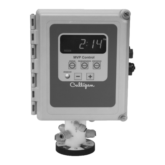
Page 11: Controller Features
Controller Features The Culligan MVP control’s (Figure 5) primary function is to initiate and control the regeneration process via methods that are most convenient and cost effective for the customer while offering many operation features and benefits. Features Power Source Electrical power required for the control is 24-Volt 50/60 Hz AC current. - Page 12 The communication input/output feature routinely recognizes when another controller within a multiple controller system is in a regeneration sequence, prohibiting the chance of multiple units regenerating simultaneously. Additionally, the Com- munication input/output feature provides the means to operate the controller in the Progressive Flow mode. Cat. No. 01016449 Culligan® CSM Series Filters...
-
Page 13: Operation
Differential Pressure When combined with an optional differential pressure device, the Culligan MVP controller has the ability to initiate a back- washing sequence when the pressure differential across the media bed reaches a preset amount (usually 8 to 10 psi). -
Page 14: Installation
Installation Figure 6. Figure 7. Figure 8. Cat. No. 01016449 Culligan® CSM Series Filters... - Page 15 CAUTION! Do Not Proceed if any distributors or laterals are broken. Consult Culligan for assistance. If any are loose, hand tighten only. Do not use a wrench. If the tank drain valve option kit was purchased, install it at this time.
- Page 16 *interconnecting piping, bypass valve and isolation valves are not supplied. NOTE Time or initiated regenerated systems do not necessarily require the use of a flow-measuring device. Therefore your system may not utilize this portion of the manual. Cat. No. 01016449 Culligan® CSM Series Filters...
- Page 17 Two popular types of flow measuring devices can be used with the controller; paddlewheel flow sensors or the Culligan in-line turbine meter. Please refer to the following chart for the number of meters required for your system configuration. Table 4.
- Page 18 It is necessary for determining the proper location for the flow sensor wheel when inserted into the fitting. Again this insert should not be removed from the tee assembly (see Figure 17). Figure 17. Cat. No. 01016449 Culligan® CSM Series Filters...
- Page 19 Copper brazolet - for use on copper pipe sizes 2-1/2” and 3”. The copper brazolet should be installed by a certified welder. A hole will need to be drilled in the pipe at the desired location as described in this section. The hole size should be 1-7/16” and must be completely deburred and free of any projections.
- Page 20 When properly loaded, the gravel should cover the distributor system in the bottom of the tank. If it does not, contact your Culligan dealer before proceeding to Step 3. Distributor...
- Page 21 If the correct type and amount of each media is not on site, contact the Culligan Dealer that sold you the filter. The media must be loaded into the mineral tank in the proper order to assure proper filter operation.
- Page 22 • From solenoid valve port number 3 to port number 4 on the pilot valve body (Fig- 26). Figure 24. Solenoid Valve Kit Blocking Solenoid for Alternating Operation Figure 25. Cat. No. 01016449 Culligan® CSM Series Filters...
- Page 23 Brunermatic Valve Figure 26. Alternating/Progressive Flow Parallel System w/ Plugged Bypass Sequence of Operation When a filter is in standby or a regeneration cycle, the MVP controller sends a signal to the P7 SOL-VIV terminal of the primary circuit board, activating the solenoid valve. The orange LED will be on at this time. When the solenoid valve is electrically activated, ports #1 and #2 of the solenoid (Figure 27) become common.
- Page 24 The fitting will grip before it seals. Make certain fitting, the tubing can be removed. the tubing is fully pushed into the tube stop. TUBE STOP O -RING C O LLET Figure 30. Figure 29. Cat. No. 01016449 Culligan® CSM Series Filters...
- Page 25 CAUTION! The port numbers on the Brunermatic valve may not coincide with the ports on the MVP pilot valve. Refer to Table 6 for cross-reference information. Table 6. Cross Reference Port Chart Pilot Valve Brunermatic Valve Brunermatic Valve Figure 31. Brunermatic Valve Figure 32.
- Page 26 NOTE One transformer is required for each controller in the system. Do not attempt to operate multiple con- trollers without a dedicated transformer for each or your system will experience operational difficul- ties. Cat. No. 01016449 Culligan® CSM Series Filters...
- Page 27 Wiring Procedures and Diagrams Preparation: Loosen the two screws securing the controller access cover (Figure 34) on each controller pro- vided. Using a small screwdriver, loosen all the terminal strip binding screws on the main circuit board that do not contain wires by turning counterclockwise until the wire clamp has been fully opened (see Figure 35).
- Page 28 Left Side View Brine Reclaim Solenoid Input Connection for Flow Sensor Output Connection for Remote Accessories Input Connection for Remote Accessories 24 Volt Power Input Connection Blocking Solenoid for Alter- nating Operation Figure 36. Cat. No. 01016449 Culligan® CSM Series Filters...
-
Page 29: Schematic
Schematic Circuit Board Layout Outputs The circuit board supports four outputs: • Motor control (P6 Motor) • Blocking valve (P7 Sol Vlv) • Two programmable auxiliary outputs (P5 Aux 1 and P8 Aux 2) • Controller interface (communication between multiple controllers) (P3 Comm). CAUTION! Do not connect the P3 communication cable to the P12 circuit board connection. - Page 30 Figure 38. Power Supply ONE transformer is required for each Control Power to circuit board 24V Power to circuit board 2.5VAC only required for Aqua-Sensor instal- lations. Not used for filtration systems. Figure 39. Cat. No. 01016449 Culligan® CSM Series Filters...
- Page 31 Communication Cable and Blocking Solenoids - Multiple Units NOTE Disregard this information and proceed to flow sensor schematic (optional) information when install- ing single tank configurations. CAUTION! Do not connect P3 communication cable to P12 circuit board connection. Doing so will damage the circuit board.
- Page 32 On twin alternating systems, part number 01016369 duplex instal- lation kit will be required. This kit contains: • One (1) interconnect cable with end connectors. • Two (2) solenoid valves with tubing and fittings. Figure 43. Cat. No. 01016449 Culligan® CSM Series Filters...
- Page 33 Flow Sensor Meter Schematic (optional) The MVP controller is capable of detecting the signal from a Hall effect sensor device to provide flow rate information, totalization and volume based regeneration initiation. The flow meter device is automatically detected when connected to the controller.
- Page 34 (user choice). These 24 vac outputs can be used for energizing a relay coil only. Refer to the section on Programming (page 40) for additional information on the uses of this feature. Figure 45. Cat. No. 01016449 Culligan® CSM Series Filters...
- Page 35 Auxiliary Input One auxiliary input (P2 Aux In) input is provided for optional signal devices such as remote push buttons, differential pres- sure switches, hardness monitors, turbid meters, etc. for the purpose of receiving a regeneration signal. Select an UN-POWERED contact within the remote device that will close when regeneration is desired. The duration of the switch closure can be as low as 0 seconds;...
-
Page 36: Programming
DIP Switches The Culligan MVP controller uses a series of ten (10) DIP Switches to streamline the programming process. Figure 47 shows the DIP Switch strip placement on the circuit board and the abbreviated text indicating the function of each switch. - Page 37 Switch Definitions The circuit board is shipped with all DIP switches in the off position. Prior to programming the controller some DIP switches may need to be moved to the ON position. Because each switch serves a specific purpose, please review the following information, moving the required switches to an ON position as necessary for each controller in the system.
- Page 38 Programming - Key Pad Familiarization Once the DIP switch settings have been established the Culligan MVP control is ready to accept user input. User input is done through the keypad on the front of the MVP circuit board. Refer to Figure 48 for a description of the layout of the keypad.
- Page 39 Multiple Unit Communication Setup Anytime two or more units are connected, each must have a specific ID # assigned. When new, a circuit board does not have an ID #. Once used, a board will have an ID # assigned and saved in EEPROM. Please refer to the appropriate paragraph concerning the establishment or re-establishment of a board ID#.
- Page 40 Program Data Input There are a couple of items to note that can make the programming the Culligan MVP control a little easier. They are: Slew Rates This term refers to the speed at which the display moves through the input of material. For exam- ple, holding down the “+”...
- Page 41 Auxiliary Input Delay* - (All modes) “AUX IN” (Figure 54) programming is required only if the AUX In terminal is being used (Such as with a differential pressure switch). This estab- lishes the uninterrupted period of time (in seconds) that a signal must be received through the auxiliary input before the controller is to react Figure 54.
- Page 42 999999). Pressing the “-” or “+” keys for 3 seconds or more will cause the digits to scroll rapidly and at intervals greater than one at a time. Figure 67. Pressing the Status key will save the setting and move to the next pro- gramming step. Cat. No. 01016449 Culligan® CSM Series Filters...
- Page 43 10. Maximum Capacity Set Point* - Only active when a flow meter is attached. Program the value that corresponds to the maximum capacity that can be expected from a unit before it is completely exhausted. If the unit reaches this set point, an immediate regeneration will occur even if the control is set to delay mode.
- Page 44 Pressing the Status key will save the setting, exit the programming mode and return to the current time display. If one control has been designated as the MASTER unit, the programming will continue as described in step 17. Cat. No. 01016449 Culligan® CSM Series Filters...
- Page 45 17. Programming Connected Controls - (Multiple Units using Communication Cabling) If multiple units are connected with the multiple communication cable AND one of the controls is designated as MASTER (DIP switch 9 set ON), the MASTER control shall be able to update the programs of other, connected controls, if the controller ID number’s have been established.
- Page 46 Program Log Use this section to record the program settings for this system. It is also suggested that additional copies be made and kept on file near the installation and with the local Culligan dealer. Program Date: Installer: Site Location:...
- Page 47 Initiating A Regeneration Cycle After all programming has been completed, the operator may elect to step each MVP control through a regeneration cycle to verify the proper operation. Perform the following steps, completing one controller at a time before moving on to the next controller (if there are more than one in the system).
-
Page 48: Statistical Data
Culligan MVP Control Statistic Functions The Culligan MVP control has the ability to provide statistical information about the system. This data is accessed through the Statistics key. To move through the statistical data available, use the “-” key. Each push of the “-” key will display new information. -
Page 49: Final Start-Up
Clean up the unit and the installation site, removing any soldering or pipe threading residues from the equip- ment with a damp towel. For units with steel tanks, place the Culligan label (packed with the media tank) on the front of the tank. Explain the operation of the filter and bypass valves to the customer. -
Page 50: Check List
‰ Clean up the unit and the installation site, removing any soldering or pipe threading residues from the equipment with a damp towel. ‰ For units with steel tanks, place the Culligan label (packed with the media tank) on the front of the tank. ‰ Explain the operation of the system and the Suggested Preventative Maintenance Inspection Schedule (page 49) to the customer. -
Page 51: Suggested Preventative Maintenance
Suggested Preventative Maintenance Sanitizing Procedure The filter should be sanitized after installation. The method of sanitization depends on the filter medium: Cullsan® media (depth filter) Household bleach (5.25% sodium hypochloride) Cullar® media (carbon filter) Caustic soda (sodium hydroxide) Preparation Prepare the filter for sanitization by depressurizing the system as indicated on page 55. - Page 52 The customer can provide most data. By collecting data prior to a service call, a “first guess” about the cause of the problem can be made and the need for any special parts can be determined. At the end of Appendix A is a recommended system data sheet that will assist the troubleshoot process. Cat. No. 01016449 Culligan® CSM Series Filters...
- Page 53 This (page 2 of this manual) provides the limits of water characteristics for the CSM Series water filters. If the water characteristics fall outside these limits, additional water treatment equipment may be required, or the water characteristics should be brought inside the limits. The system flow rates and exchange capacities are also listed.
-
Page 54: Diagnostics
Culligan MVP Control Test Functions The Culligan MVP control has a diagnostic feature that allows the user to verify the operation of the board components. Moving DIP switch 1 from “R” (Run) to “T” (Test) or the ON position enters the test mode. (See... - Page 55 The following chart provides a description, display information and the required action to trigger the next step of the test mode. Test Description Display Information Action Trigger Start Test Mode All LCD segments lit DIP switch #1 set to on, all others off Verify software Software version # Press a key after entering test mode...
-
Page 56: Troubleshooting Guide
Inlet water pressure may be low. • Backwash flow control may be plugged. • If flow rate in position 3 is greater than position 1 then valves #2 and #5 are not functioning properly. Cat. No. 01016449 Culligan® CSM Series Filters... - Page 57 PROBLEM OR CHECK PROCEDURE CAUSE SYMPTOM Media to Service Check tank distribution system Broken lateral Bad distributor. Media to Drain High flow of water to drain. Check/replace backwash flow control washer(s). Air in system Air from source other than water softener. Elimi- nate source of air or install air vent in top of tank.
- Page 58 You may also power down the control for 60 seconds or toggle a DIP switch. If the problem is still present after attempting to clear the error code, the code will remain in the display. Cat. No. 01016449 Culligan® CSM Series Filters...
-
Page 59: Service
Service Procedure for Depressurizing the Brunermatic Valve and System for Service Complete shut down procedure is as follows: Disconnect the electrical power to the MVP controller. Make certain that the lines you shut off are for the system you are performing service on. Open by-pass valve if one is available. - Page 60 Evidence of the old numbering scheme is noted by the use of port number 17 on the pilot valve and/or Brunermatic valve. If the numbering scheme of the pilot valve does not completely match the Brunermatic valve, the following chart should be referred to for conversion purposes. Cat. No. 01016449 Culligan® CSM Series Filters...
- Page 61 Backwash Flow Controllers - Theory of Operation and Service Located on the drain connection of the Brunermatic valve, the purpose of the backwash flow controller is to regulate the up flow backwash required to expand and agitate the media in the filter. The filter will allow maximum expansion of the media, while preventing any loss to the drain.
- Page 62 Connect the flexible tubing to the compression fitting located in the side of the Backwash Flow Control nipple. Figure 92. Insert and tighten clean-out plug. (Figure 91) Figure 93. Figure 94. Figure 95. Cat. No. 01016449 Culligan® CSM Series Filters...
- Page 63 Pilot Valve Spool Removal & Replacement Close the manual inlet isolation valve, the manual outlet isolation valve, and any external source of pressure to the pilot valve assembly. Follow the instructions on page 55 for depressurizing the system before proceed- ing.
- Page 64 Reinstall the pilot valve body assembly in the enclosure. Make certain the pilot valve position faces left when viewed from the front of the controller. Reconnect the four quick connect wire leads to the microswitches. Connect the two motor leads to the circuit board. Reconnect all pilot valve tube connections. Cat. No. 01016449 Culligan® CSM Series Filters...
- Page 65 Pilot Valve Assembly Replacement NOTE The cam gear is designed to only be installed one way onto the pilot valve spool. The flat portion of the pilot valve spool must align with the flat side of the cam gear’s pilot receptacle. When properly positioned, the cam will snap into place on the pilot valve spool.
-
Page 66: Service Parts
Service Parts CSM Series Filter Parts List The following section includes all available replacement parts for the CSM product line. This list is divided into the following sections: Section 1 - Replacement Media Tank and Supporting Parts. Section 2 - Brunermatic Valve, and Backwash Flow Controller. -
Page 67: Cat. No.
Section 1 - Replacement Resin Tank and Support Parts Standard Replacement Tank Assembly* Tanks 20-30” are supplied with a hand-hole in the top and lower sideshell. Tanks 36” diameter and larger are supplied with a manhole in the top and no hand-hole in the side. All tanks are equipped with non- adjustable steel legs welded to tank and come with upper distributor and hub radial lower distributor system installed in the tank. - Page 68 Cat. No. 01016449 Culligan® CSM Series Filters...
- Page 69 Tank Internals Item #3 Tank Assy Carbon Filters Item #4 Laterals - Qty Non-Code ASME Code CSM-242R 01020121 01020129 01020033-8 CSM-302R 01020122 01020130 01020034-8 CSM-362R 01020124 01020132 01020035-8 CSM-422R 01020126 01020134 01020036-8 Item #3 Tank Assy Depth Filters Item #4 Laterals - Qty Non-Code ASME Code CSM-202D...
- Page 70 A1127006 30 GPM CSM-242D 01017241 2” A1128020 45 GPM CSM-302D 01017241 2” A1128026 75 GPM CSM-362D 01017241 2” 01011852 105 GPM CSM-422D 01017241 2” 01011854 150 GPM CSM-423D 01017242 3” 01011854 150 GPM Cat. No. 01016449 Culligan® CSM Series Filters...
- Page 71 Section 3 Brunermatic® D-180 Multiport Valve 2” The Brunermatic® D-180 Multiport Valve assemblies that are covered in this section are listed below. All valve assem- blies listed are for cold water application only. Valve Part No. Thread Size Type of Thread 01017241 2”...
- Page 72 Kit, Diaphragm Cover, 01017403 01017407 Includes Cover, Fitting and Hardware Kit, O-Ring Replacement, Guide Cage, Includes 5 ea. O-Rings for Diaphragm Guide A1013387 Cages and 1 ea. O-Ring for the By-pass Guide Cage. Cat. No. 01016449 Culligan® CSM Series Filters...
- Page 73 Brunermatic® D-180 Multiport Valve 3” The Brunermatic® D-180 Multiport Valve assemblies that are covered in this section are listed below. All valve assem- blies listed are for cold water application only. VALVE PART NO. THREAD SIZE TYPE OF THREAD 01017242 3”...
- Page 74 6. Also, 5 Spring Guides. Kit, Diaphragm Cover, 01017404 01017405 Includes Cover, Fitting and Hardware Kit, O-Ring Replacement, Guide Cage, Includes 5 O-Rings for Diaphragm Guide Cages A1013388 and 1 O-Ring for the Bypass Guide Cage. Cat. No. 01016449 Culligan® CSM Series Filters...
- Page 75 Section 4 Culligan MVP Valve Mounted Controller Cat. No. 01016449 Service Parts...
- Page 76 Culligan MVP Valve Mounted Controller Parts List Item Qty. Needed Description Replacement Kit Per Controller Part # Qty. Per Package — Controller - Complete (Does not include items 11 or 01016170 Controller - Enclosure with Plugs & Membrane Switch 01016368...
-
Page 77: Appendix A Flow Device K-Factor Data
Appendix A Flow Device K-Factor Data Figure 102. Turbine Meter Figure 103. Blue Nut Meter Installation Fitting Pipe Flow Range (Gal Per Min) K-Factor - Gallons Type Type (if applicable) Size Turbine 1.5” 1 - 60 67.0 (if installed 16” or more from valve) Turbine 1.5”... -
Page 78: Appendix B Separate Source Assembly
Cut the included control tubing to length, and connect as shown in the illustrations on following page (Figure 107 & Figure 108). Figure 104. Figure 105. Figure 106. NOTE These four fittings are assembled hand tight for reassembly on site. Cat. No. 01016449 Culligan® CSM Series Filters... - Page 79 MAIN INLET WATER INLET ISOLATION VALVE* PILOT VALVE INLET DIAPHRAGM ISOLATION VALVE VALVE* SEPARATE SOURCE CHECK WATER VALVE Figure 107. Single System with Bypass MAIN INLET WATER INLET ISOLATION VALVE INLET ISOLATION DIAPHRAGM VALVE VALVE SEPARATE SOURCE CHECK WATER VALVE VALVE Figure 108.
-
Page 80: Program Log
Program Log Program Log Use this section to record the program settings for this system. It is also suggested that additional copies be made and kept on file near the installation and with the local Culligan dealer. Program Date: Installer:... - Page 81 Notes Cat. No. 01016449 Notes...
- Page 82 Cat. No. 01016449 Culligan® CSM Series Filters...
Need help?
Do you have a question about the CSM Series and is the answer not in the manual?
Questions and answers