
Related Manuals for Festo CPX-FEC


Summary of Contents for Festo CPX-FEC
- Page 1 CPX terminal Electronics manual CPX−Front−End Controller Type CPX−FEC Manual 538 475 en 0404NH [677 480]...
- Page 3 ....... . . 538 475 E (Festo AG & Co. KG, D 73726 Esslingen, Federal Republic of Germany, 2004) Internet: http://www.festo.com...
- Page 4 Contents and general instructions MODBUSt Registered trade mark of Schneider Automation Microsoft Windowst Registered trade mark of Microsoft Corporation Microsoft Internet Explo Registered trade mark of Microsoft Corporation Festo P.BE−CPX−FEC−EN en 0404NH...
-
Page 5: Table Of Contents
........2−18 Compliance with protection class IP65/IP67 ......2−19 Festo P.BE−CPX−FEC−EN en 0404NH... - Page 6 Data exchange on layers 1 to 4 ......4−9 Festo P.BE−CPX−FEC−EN en 0404NH...
- Page 7 ........6−26 6.2.6 Addressing examples for Modbus/TCP ..... . 6−26 Festo P.BE−CPX−FEC−EN en 0404NH...
- Page 8 ........D−24 Festo P.BE−CPX−FEC−EN en 0404NH...
- Page 9 ............E−1 Festo P.BE−CPX−FEC−EN en 0404NH...
-
Page 10: Designated Use
Observe also the standards specified in the relevant chapters, as well as national and local laws and technical regulations. VIII Festo P.BE−CPX−FEC−EN en 0404NH... -
Page 11: Target Group
Ethernet and the relevant field bus protocols. Service Please consult your local Festo repair service if you have any technical problems. Festo P.BE−CPX−FEC−EN en 0404NH... -
Page 12: Notes On The Use Of This Manual
Please note This manual refers to the following versions: Hardware/software Version CPX−FEC as from software status 31.03.2004 Festo Software Tools (FST) Version 4.1 or higher CPX−FB06 Interbus as from software status 11.07.2003 CPX−FB11 DeviceNet as from software status 06.10.2003 CPX−FB13 PROFIBUS−DP as from software status 26.02.2004... -
Page 13: Important User Instructions
This means that failure to observe this instruction may result in damage to property. The following pictogram marks passages in the text which describe activities with electrostatically sensitive compo nents. Electrostatically sensitive components may be damaged if they are not handled correctly. Festo P.BE−CPX−FEC−EN en 0404NH... - Page 14 Accessories: Information on necessary or sensible accessories for the Festo product. Environment: Information on environment−friendly use of Festo products. Text markings The bullet indicates activities which may be carried out in · any order. 1. Figures denote activities which must be carried out in the numerical order specified.
- Page 15 Information on fitting, installing and commis CPA pneumatics" sioning CPA pneumatics (type 12) type P.BE−CPA−... Valve terminals with Instructions on fitting, installing and commis Midi/Maxi pneumatics" sioning Midi/Maxi pneumatics (type 03) type P.BE−MIDI/MAXI−03−... Tab. 0/2: Manuals on the CPX terminal XIII Festo P.BE−CPX−FEC−EN en 0404NH...
- Page 16 Digital inputs and outputs OB, OW Output byte, output word PLC/IPC Programmable logic controller/industrial PC Pneumatic interface The pneumatic interface is the interface between the modular electrical peripherals and the pneumatics. Tab. 0/3: Product−specific terms and abbreviations Festo P.BE−CPX−FEC−EN en 0404NH...
- Page 17 DHCP Dynamic protocol for automatic assignment of IP addresses (Dynamic Host Configuration Protocol) EasyIP Protocol for the fast exchange of operands between Festo controllers (e.g. FEC Standard, PS1, etc.). Ethernet Physical protocol and network for connecting various devices FTP, TFTP...
-
Page 18: System Summary
System summary Chapter 1 1−1 Festo P.BE−CPX−FEC−EN en 0404NH... -
Page 19: Programming The Cpx−Fec
....... . . 1−12 Tutorial: Creating a project for the CPX−FEC with FST (Stand Alone) ..1−15 1−2 Festo P.BE−CPX−FEC−EN en 0404NH... - Page 20 I/O modules, descriptions of the field bus node the FST manual (2 volumes, supplied with the FST software) text book Automation with FST" (supplied with the FST software) manuals on the pneumatics (MPA, CPA, CPV, Midi/Maxi) 1−3 Festo P.BE−CPX−FEC−EN en 0404NH...
- Page 21 Here is an overview of the possibilities which are offered: The CPX−FEC can control a CPX terminal independently (Stand Alone). Use the Festo Software Tool FST 4.1 with the Hardware Configurator for commissioning, program ming and diagnosis.
-
Page 22: The Operating Modes Of The Cpx−Fec
The operating mode can be set with DIL switch 1 (see section 2.2.2). You can connect a handheld of type CPX−MMI to the CPX−FEC in any operating mode. The handheld serves for fast prelimi nary commissioning, parametrizing and diagnosis. 1−5 Festo P.BE−CPX−FEC−EN en 0404NH... - Page 23 CPX−FEC. There is no communication connection to other slaves. Configure the CPX terminal with the FST software package FST 4.1 or higher. The programming or Ethernet interface can be used for the configuration. Fig. 1/2: Software package FST 4.1 for configuration 1−6 Festo P.BE−CPX−FEC−EN en 0404NH...
- Page 24 A field bus node (with DIL switch position for Remote Controller") must be installed in the CPX terminal for this operating mode. Configure the CPX terminal with FST. 1−7 Festo P.BE−CPX−FEC−EN en 0404NH...
-
Page 25: Remote I/O
Ethernet automation systems (e.g. Schneider Electric). You can use the integrated Webserver for control, diagnosis and communication. An advantage of this operating mode is that you only need to use one bus system. 1−8 Festo P.BE−CPX−FEC−EN en 0404NH... - Page 26 A field bus node in the operating mode Remote Controller" must also be installed here in the CPX terminal. The Webserver can occupy free memory space in the PLC if extra memory space is required. Tab. 1/1: Overview of the operating modes 1−9 Festo P.BE−CPX−FEC−EN en 0404NH...
-
Page 27: Programming The Cpx−Fec
Fig. 1/3: Programming with FST 4.1 You can find detailed information on programming the CPX− FEC in the following documentation: the FST manual (supplied with the FST software) the text book Automation with FST" (supplied with the FST software). 1−10 Festo P.BE−CPX−FEC−EN en 0404NH... -
Page 28: Meaning Of The Led Displays
Ethernet LEDs (see chapters 3, 5 and 6): STOP ERROR CPX−LEDs (see next section): PS: Power system PL: Power load SF: System fault M: Modify Fig. 1/4: Two groups of the LEDs of the CPX−FEC 1−11 Festo P.BE−CPX−FEC−EN en 0404NH... -
Page 29: Fault Displays Of The Leds
(default) Power Off/On is necessary · The operating voltage/ Check the operating voltage sensor supply is not connection of the electronics applied LED is out Tab. 1/2: Fault diagnosis with the LED PS 1−12 Festo P.BE−CPX−FEC−EN en 0404NH... - Page 30 The system fault LED flashes depending on the class of fault which has occurred. Fault class 1 (simple fault): one flash, pause Fault class 2 (fault): flash twice, pause Fault class 3 (serious fault): flash three times, pause Tab. 1/4: Fault diagnosis with the LED SF 1−13 Festo P.BE−CPX−FEC−EN en 0404NH...
- Page 31 LED lights up" does not exist with LED lights up the M−LED. Tab. 1/5: Messages of the LED M Information on the controller and Ethernet LEDs RUN, STOP, ERROR and TP can be found in chapters 3...6. 1−14 Festo P.BE−CPX−FEC−EN en 0404NH...
-
Page 32: Tutorial: Creating A Project For The Cpx−Fec With Fst (Stand Alone)
6. Open the Hardware Configurator with a double click on I/O Configuration" in the project window. 7. Select Actual−Nominal−Comparison" in the context menu (right−hand mouse click) of the Hardware Configurator. Accept the configuration by clicking on Apply". 1−15 Festo P.BE−CPX−FEC−EN en 0404NH... - Page 33 1. System summary Fig. 1/5: Carry out the actual−nominal comparison Fig. 1/6: Apply the actual−nominal comparison 1−16 Festo P.BE−CPX−FEC−EN en 0404NH...
- Page 34 1. System summary Fig. 1/7: A configured CPX terminal 8. If necessary, parametrize the CPX system or individual modules: Fig. 1/8: Example: Parametrizing an input module 1−17 Festo P.BE−CPX−FEC−EN en 0404NH...
- Page 35 2. Select the programming language (e.g. Statement List) in the window New program". 3. Confirm the next window without modifications (Type program, Number 0, Version 1). 4. Create a program: Fig. 1/9: Program window of the FST 1−18 Festo P.BE−CPX−FEC−EN en 0404NH...
- Page 36 6. The new program is marked for loading automatically in the project window. Load the project into the CPX−FEC with [Online] [Download Project]: Fig. 1/11: A marked program is loaded into the FEC with the project 1−19 Festo P.BE−CPX−FEC−EN en 0404NH...
- Page 37 1. System summary Start program 7. Set the rotary switch of the CPX−FEC to 1...F or start the program in the Online TCPIP" display: Fig. 1/12: Program start with the Online TCPIP" display 1−20 Festo P.BE−CPX−FEC−EN en 0404NH...
-
Page 38: Installation
Installation Chapter 2 2−1 Festo P.BE−CPX−FEC−EN en 0404NH... - Page 39 ........2−18 Compliance with protection class IP65/IP67 ......2−19 2−2 Festo P.BE−CPX−FEC−EN en 0404NH...
- Page 40 CPX pneumatic interface and CPX I/O modules (P.BE−CPX−EA−..) Handheld: Manual for the universal handheld CPX−MMI−1 (P.BE CPX−MMI−1−..) Instructions on installing the pneumatic components can be found in the relevant pneumatics manual (see Tab. 0/2). 2−3 Festo P.BE−CPX−FEC−EN en 0404NH...
-
Page 41: General Notes On Installation
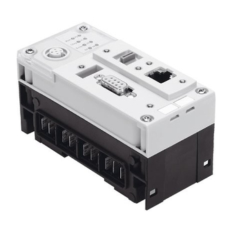
· Observe the regulations for handling electrostatically · sensitive components. In this way you will avoid damage to the electronics. Information on fitting the CPX terminal can be found in the CPX system manual (P.BE−CPX−SYS−..). 2−4 Festo P.BE−CPX−FEC−EN en 0404NH... - Page 42 (RUN/STOP, Program selection) 2−element DIL switch 2 (reserved) Ethernet interface Service interface for handheld (V24) (10/100BaseT, RJ45) Programming interface (RS232, 9−pin sub−D socket) Fig. 2/1: Connecting and display elements on the CPX field bus node 2−5 Festo P.BE−CPX−FEC−EN en 0404NH...
- Page 43 1. Loosen the four screws of the FEC with a Torx screwdriver size T10. 2. Pull the FEC carefully and without tilting away from the contact rails of the manifold sub−base. CPX−FEC Manifold sub−base Contact rails Torx T10 screws Fig. 2/2: Dismantling/fitting the CPX−FEC 2−6 Festo P.BE−CPX−FEC−EN en 0404NH...
- Page 44 2. Insert the screws so that the self−boring threads can be used. Tighten the screws at first only by hand. Tighten the screws with a Torx screwdriver size T10 with 0.9 ... 1.1 Nm. 2−7 Festo P.BE−CPX−FEC−EN en 0404NH...
-
Page 45: Setting The Switches Of The Fec
Programs start when the rotary switch is modified from 0 to 1 ... F. The switch position can be interrogated in the user program and used for programming purposes. Tab. 2/1: Possible settings of the rotary switch for the PLC 2−8 Festo P.BE−CPX−FEC−EN en 0404NH... -
Page 46: Dil Switches
Remove an IP65/IP67 plug, if fitted, from the program · ming interface. Setting the operating mode with DIL switch 1 You can set the operating mode of the FEC with switch element 1 of DIL switch 1. 2−9 Festo P.BE−CPX−FEC−EN en 0404NH... - Page 47 Reserved DIL 1.1: ON DIL 1.2: ON Reserved DIL 1.1: ON DIL 1.2: OFF Tab. 2/2: Setting the operating mode Reserved DIL switch 2 Leave the switch elements of DIL switch 2 set to OFF. 2−10 Festo P.BE−CPX−FEC−EN en 0404NH...
-
Page 48: Ethernet Interface
0.89 ... 1.0 mm AWG24−26 ready made: Crimping pliers on RJ45 Please note If the CPX terminal is fitted onto a moving part of a machine, the Ethernet cable on the moving part must be provided with strain relief. 2−11 Festo P.BE−CPX−FEC−EN en 0404NH... - Page 49 PC and the CPX−FEC. Please note Use the RJ45 plug from Festo in order to comply with protection class IP65/IP67. Type FBS−RJ45−8−GS, part no. 534494 Observe the fitting instructions for the plug.
-
Page 50: Programming Interface (Rs232)
Connection to functional earth Tab. 2/4: Pin assignment of the programming interface If the programming interface is not used, seal it with the transparent cover. type AK−SUB−9/15−B part no. 533334 max. tightening torque 0.4 Nm 2−13 Festo P.BE−CPX−FEC−EN en 0404NH... -
Page 51: Connecting A Programming Pc
2. Installation 2.4.2 Connecting a programming PC Use the programming cable from Festo in order to connect your PC to the CPX−FEC: type KDI−PPA−3−BU9 part no. 151915 Please note Use the above programming cable only for the program ming environment. It has only one screening connection on one side and complies only with protection class IP20. - Page 52 Festo (Fig. 2/4) type FBS−SUB−9−GS−1X9POL−B a 3−core screened cable. Please note Only the programming plug from Festo guarantees com pliance with protection class IP65/IP67. If you also need to comply with protection class IP65/IP67 in the program ming environment: Relpace the two flat screws by threaded sleeves (type ·...
- Page 53 Terminal strip for the cable (pin assignment see Tab. 2/4) Fastening screws Fig. 2/4: Programming plug from Festo, type FBS−SUB−9−GS−1X9POL−B Please note Use protective caps or blanking plugs to seal unused · connections. In this way you will comply with protection class IP65/IP67.
-
Page 54: Connecting The Front End Display Fed−50/90
FED operating devices are intended for fitting in the front of a metallic housing. Fig. 2/5: CPX terminal with FED−90 Connect the FED to the CPX−FEC with connecting cable · type FEC−KBG7 or FEC−KBG8 (part no. 539642 resp. 539643). 2−17 Festo P.BE−CPX−FEC−EN en 0404NH... -
Page 55: Service Interface For Handheld
Type Cable length in [m] KV−M12−M12−3,5 KV−M12−M12−1,5 Tab. 2/5: Connecting cable for handheld Information on the handheld can be found in the manual Universal handheld type CPX−MMI−1". Fig. 2/6: CPX terminal with handheld 2−18 Festo P.BE−CPX−FEC−EN en 0404NH... -
Page 56: Compliance With Protection Class Ip65/Ip67
Protective cap plug for the handheld type ISK−M12 part no. 352059 Rotary switch Cover type AK−RJ45 part no. 534496 If connection is not used Included in delivery Tab. 2/6: Connections and covers for protection class IP65/IP67 2−19 Festo P.BE−CPX−FEC−EN en 0404NH... - Page 57 2. Installation 2−20 Festo P.BE−CPX−FEC−EN en 0404NH...
-
Page 58: General Operation (Stand Alone)
General operation (Stand Alone) Chapter 3 3−1 Festo P.BE−CPX−FEC−EN en 0404NH... - Page 59 Access and control via CI commands ....... 3−61 3−2 Festo P.BE−CPX−FEC−EN en 0404NH...
- Page 60 1. Configuring the CPX terminal with FST 2. If desired: Parametrize 3. Create program 4. Load project into CPX−FEC 5. Start and test program Various diagnostic possibilities are available during commis sioning and during operation. 3−3 Festo P.BE−CPX−FEC−EN en 0404NH...
-
Page 61: Configuration
3. General operation (Stand Alone) Configuration Use Festo Software Tools (FST 4.1 or higher) with the Hard ware Configurator in order to configure your CPX terminal with CPX−FEC. In the following sections you will find the most important commissioning steps with FST 4.1. -
Page 62: Creating A Project
4. Confirm with OK. 3.1.2 Creating a project Create a new project in FST as follows: 1. [Project] [New...] 2. Assign a project name. 3. Select the CPX−FEC as controller in the window Project Settings". 3−5 Festo P.BE−CPX−FEC−EN en 0404NH... - Page 63 If the Hardware Catalogue is not displayed: Select [View] [Catalog]. Please note Note the register Download" in the Controller settings". Select Download source files" if you wish to download · the project later from the CPX−FEC (e.g. on another PC). 3−6 Festo P.BE−CPX−FEC−EN en 0404NH...
- Page 64 When a new project is created with the CPX−FEC, a CPX−FEC will automatically be numbered module 0: Project window Hardware Catalogue Hardware Configurator Configuration table Fig. 3/2: FST 4.1 with Hardware Configurator after creation of a new project 3−7 Festo P.BE−CPX−FEC−EN en 0404NH...
-
Page 65: Fast Configuration By Loading The Actual Configuration
(mapping) or the Idle mode/Fail safe set tings are to be transferred. 4. Click on Apply" in order to transfer the selection to the current project. The Hardware Configurator remains in the editor mode. 3−8 Festo P.BE−CPX−FEC−EN en 0404NH... - Page 66 The configuration of the CPX terminal will be loaded and transferred to the Hardware Configurator. 2. Select [Save] in the context menu, in order to save the loaded configuration in your project. The Hardware Configurator is now connected online with the CPX terminal. 3−9 Festo P.BE−CPX−FEC−EN en 0404NH...
-
Page 67: Manual Configuration With The Hardware Configurator
2. The addresses will be assigned automatically in accord ance with the default addressing. Modifying addresses: Click directly on the address in the configuration table and modify the value. Deleting modules Mark the module to be deleted and press the Del" · button. 3−10 Festo P.BE−CPX−FEC−EN en 0404NH... - Page 68 3. General operation (Stand Alone) Configuration with drag & drop Configured modules in the configuration table Fig. 3/4: Manual configuration of the CPX terminal in the Hardware Configurator 3−11 Festo P.BE−CPX−FEC−EN en 0404NH...
- Page 69 The inputs form the position of 1 word O the rotary switch. The outputs are not used. 1) Module identifiers on the handheld and in the Hardware Configurator of the FST 4.1 Tab. 3/1: Module CPX−FEC 3−12 Festo P.BE−CPX−FEC−EN en 0404NH...
- Page 70 Assigned address Remarks identifiers range CP interface max. 8 words I The number of assigned addresses max. 8 words O depends on the string assignment saved in the CP interface. Tab. 3/3: Technology module CP interface 3−13 Festo P.BE−CPX−FEC−EN en 0404NH...
- Page 71 1...24 valve coils: 2 words O 1...26 valve coils: 2 words O Module identifiers on the handheld and in the Hardware Configurator of the FST 4.1 Tab. 3/4: Overview of pneumatic interfaces and MPA pneumatic modules 3−14 Festo P.BE−CPX−FEC−EN en 0404NH...
- Page 72 2. Double click on the line. The window Module..." will be displayed. 3. Switch to the register Module" and select the number of valve coils as is set on the DIL switch in the pneumatic interface: 3−15 Festo P.BE−CPX−FEC−EN en 0404NH...
- Page 73 The same number of valves is displayed as the number of outputs which are set, irrespective of whether there are single−solenoid valves or double−solenoid valves in your CPX terminal. 3−16 Festo P.BE−CPX−FEC−EN en 0404NH...
- Page 74 A successful configuration is distinguished by: module assignment without gaps clear assignment of the master pneumatic modules are situated at the right−hand end of the CPX terminal Check the configuration Click on Check Configuration" in the context menu: · 3−17 Festo P.BE−CPX−FEC−EN en 0404NH...
- Page 75 Module parameter without Idle mode and Fail safe Mapping Address assignment of the CPX terminal Idle mode/Fail safe Idle mode and Fail safe parameters System settings System parameters and diagnostic memory parameters Tab. 3/5: Options Reset configuration 3−18 Festo P.BE−CPX−FEC−EN en 0404NH...
-
Page 76: Addressing
Valves / pneumatic modules 32 ... 63 Analogue inputs and outputs 64 ... 127 64 ... 127 FEC, bus node, technology module 128 ... 255 128 ... 255 Tab. 3/6: Pre−assigned address ranges of default addressing 3−19 Festo P.BE−CPX−FEC−EN en 0404NH... -
Page 77: Individual Addressing
Make sure that the new address is not already assigned, otherwise you will receive a fault message. Fig. 3/7: Modify address in the Hardware Configurator (here with fault message because address is already assigned) 3−20 Festo P.BE−CPX−FEC−EN en 0404NH... -
Page 78: Addressing Example
Example 1: CPX terminal with default addressing CPX−FEC Analogue I/O modules Digital I/O modules MPA pneumatics (3 pneumatic modules) Fig. 3/8: Example 1: CPX terminal with digital and analogue I/O modules as well as MPA pneumatics 3−21 Festo P.BE−CPX−FEC−EN en 0404NH... - Page 79 (2AO) MPA pneumatic interface Passive module, is not (type VMPA−FB−EPL−...) shown in the FST MPA pneumatic module (CPX−type32: 1...8V) MPA pneumatic module (CPX−type32: 1...8V) MPA pneumatic module (CPX−type32: 1...8V) Tab. 3/7: Configuration of example 1 3−22 Festo P.BE−CPX−FEC−EN en 0404NH...
- Page 80 Light grey: assigned but not used Word number, automatically assigned by the default addressing Rotary switch of the CPX−FEC (interrogation of the switch position possible in user program) Tab. 3/8: Address assignment for example 1 (default addressing) 3−23 Festo P.BE−CPX−FEC−EN en 0404NH...
- Page 81 For the 2nd. addressing example the addresses have been modified so that inputs and outputs or valves lie together in blocks. It is then easier e.g. to understand the composition of machines (sensors, outputs and valves) in the addressing table. 3−24 Festo P.BE−CPX−FEC−EN en 0404NH...
- Page 82 (2AO) MPA pneumatic interface Passive module, is not (type VMPA−FB−EPL−...) shown in the FST MPA pneumatic module (CPX−type32: 1−8V) MPA pneumatic module (CPX−type32: 1−8V) MPA pneumatic module (CPX−type32: 1−8V) Tab. 3/9: Configuration of example 2 3−25 Festo P.BE−CPX−FEC−EN en 0404NH...
- Page 83 Light grey: assigned but not used Word number, automatically assigned by the default addressing Rotary switch of the CPX−FEC (interrogation of the switch position possible in user program) Tab. 3/10: Address assignment for example 2 (modified addressing) 3−26 Festo P.BE−CPX−FEC−EN en 0404NH...
-
Page 84: Parametrizing
CPX system manual (P.BE−CPX−SYS−..). The module parameters which are available for the various modules can be found in the manual for the relevant module (e.g. manual for CPX pneumatic interface and CPX I/O mod ules (P.BE−CPX−EA−..). 3−27 Festo P.BE−CPX−FEC−EN en 0404NH... - Page 85 CPX terminal and is lost with Power entries with the handheld. OFF/ON User programs Access via function mod Program−controlled reaction dules (see appendix C.1) Preprocessing possible Programming very costly Tab. 3/11: Properties of the different parametrizing possibilities 3−28 Festo P.BE−CPX−FEC−EN en 0404NH...
-
Page 86: Parametrizing With The Handheld
(online): Parameters can be transferred immediately. However, parameters are saved only locally in the CPX terminal and are lost with Power OFF/ON. When the relevant dialogue has been opened, you can view and modify the individual parameters. 3−29 Festo P.BE−CPX−FEC−EN en 0404NH... - Page 87 2. They are not saved in the project. Parametrizing Handheld from the FEC Configurator project at start: The parameter set is distributed amongst modules Parametrizing as Project a test function with the handheld Fig. 3/10: Sequence of start parametrizing 3−30 Festo P.BE−CPX−FEC−EN en 0404NH...
- Page 88 System parameters 1. Click on System Settings" in the context menu of the Hardware Configurator. 2. Set the system parameters in the register System Para meters": Fig. 3/11: Set the system parameters with the Hardware Configurator 3−31 Festo P.BE−CPX−FEC−EN en 0404NH...
- Page 89 Module parameters 1. Double click on the module in the Hardware Configurator which you wish to parametrize. 2. Set the desired parameters in the register Parameters": Fig. 3/12: Set the module parameters with the Hardware Configurator 3−32 Festo P.BE−CPX−FEC−EN en 0404NH...
- Page 90 1. Click on System Settings" in the context menu of the Hardware Configurator. 2. Set the diagnostic memory parameters in the register Trace Parameters". Fig. 3/13: Set the diagnostic memory parameters with the Hardware Configurator 3−33 Festo P.BE−CPX−FEC−EN en 0404NH...
-
Page 91: Parametrizing From A User Program
Tab. 3/12: Function modules for parametrizing the CPX terminal Further information on function modules and on parametriz ing from a user program can be found in: the appendix C.1 in the FST system manual under Drivers and modules". 3−34 Festo P.BE−CPX−FEC−EN en 0404NH... -
Page 92: Forcing
The online display of the FST does not show the forced, physical output signal, but the status from the processing image. 3−35 Festo P.BE−CPX−FEC−EN en 0404NH... - Page 93 If you block or enable forcing globally, all signal states which are forced will become ineffective or effective im mediately. 1. Use the right−hand mouse button to click the module for which you wish to set the force parameters. 2. Select [Properties]. 3−36 Festo P.BE−CPX−FEC−EN en 0404NH...
- Page 94 Forcing via CI commands Information on forcing with CI commands can be found in appendix D and in the chapter 2 Basic functions of the FST software" in volume 1 of the FST manual. 3−37 Festo P.BE−CPX−FEC−EN en 0404NH...
-
Page 95: Application Example For The Parametrizing
0.1 ms: Shorter signals can also be registered (applies to the complete module). Modification of the signal lengthening time to 50 ms: The signal will be registered reliably by the controller.(applies only to the input channel of the 2nd. sensor). 3−38 Festo P.BE−CPX−FEC−EN en 0404NH... -
Page 96: Programming The Cpx−Fec
When you have planned and structured a project, you can start with programming. The following are required: operands (retentive, non−retentive) operations (set of commands) function modules (depending on application). 3−39 Festo P.BE−CPX−FEC−EN en 0404NH... -
Page 97: Overview Of Operands
Counter word CW0 ... CW255 Register R0 ... R255 Function units FU0 ... FU31, FU39 ... FU255 per program Function units FU32 ... FU38 per program Programs P0 ... P63 Program status PS0 ... PS63 3−40 Festo P.BE−CPX−FEC−EN en 0404NH... -
Page 98: Overview Of Operations
3. General operation (Stand Alone) Operand Design. Range Retentive Function modules CFM0 ... CFM99 (predefined by Festo) Program modules CMP0 ... CMP99 (user−defined) Tab. 3/13: Operands CPX−FEC Retentive operands retain their value even when the controller is switched off. 3.4.2 Overview of operations Depending on the programming language selected (STL or LDR), various operands are available for creating a program. - Page 99 Negation: Negates operands, i.e. they are interrogated for logical zero Logical command for bit−by−bit AND linking Logical command for bit−by−bit OR linking EXOR EXOR Logical command for bit−by−bit exclusive OR linking Tab. 3/14: Overview of operations of the CPX−FEC (part 1) 3−42 Festo P.BE−CPX−FEC−EN en 0404NH...
- Page 100 Complements multibit operands according to the method of the 1st. complement. Complements multibit operands according to the method of the 2nd. complement. Tab. 3/15: Overview of operations of the CPX−FEC (part 2) 3−43 Festo P.BE−CPX−FEC−EN en 0404NH...
- Page 101 When modules are accessed, the parameter transfer is started (CMP ... WITH ...) JMP TO (via jump marks) Jump to a jump mark, instruction follows in an executive part. Tab. 3/16: Overview of operations of the CPX−FEC (part 3) 3−44 Festo P.BE−CPX−FEC−EN en 0404NH...
-
Page 102: Overview Of Function Modules For The Cpx Terminal
Tab. 3/17: Function modules for parametrizing the CPX terminal Modules Description C_STATUS Interrogate diagnostic status C_TR_rd Read entries in diagnostic memory C_MD_rd Read module diagnostic data Tab. 3/18: Function modules for diagnosing the CPX terminal 3−45 Festo P.BE−CPX−FEC−EN en 0404NH... -
Page 103: User Programs
Programs are always part of a project and will therefore be loaded into the CPX−FEC with the complete project. Load the project into the CPX−FEC: 1. In the project window mark the program which you wish to load into the FEC: 3−46 Festo P.BE−CPX−FEC−EN en 0404NH... - Page 104 4. In order to stop the program (see FST system manual): Turn the rotary switch to 0" or stop the program: with the online control panel or in the online display in the register Programs" or with a CI command. 3−47 Festo P.BE−CPX−FEC−EN en 0404NH...
- Page 105 If there is a fault, the output will be set for as long as the fault lasts. Error program Defines the program which is to be started when there is a fault. 0" stands for No error program". Tab. 3/19: Set the run mode behaviour of the controller 3−48 Festo P.BE−CPX−FEC−EN en 0404NH...
- Page 106 3. General operation (Stand Alone) Fig. 3/16: Set the run mode behaviour of the controller Further information can be found in the FST manual. 3−49 Festo P.BE−CPX−FEC−EN en 0404NH...
-
Page 107: Program Example (Stl)
Ejected ’Ejector is at front Fig. 3/17: Program example Extract from a drilling machine controller The symbolic operands (Untensioned", Drill_above", ...) will be linked to the absolute operands (I0.0, O0.0, ...) via the allocation list: 3−50 Festo P.BE−CPX−FEC−EN en 0404NH... - Page 108 3. General operation (Stand Alone) Fig. 3/18: Assignment list for the programming example from Fig. 3/17 3−51 Festo P.BE−CPX−FEC−EN en 0404NH...
-
Page 109: Diagnosis
Error word EW > 0 With function modules program Complete diagnostic information (see section 3.5.3 and appendix C.1) Program−controlled reaction to faults Display on FED/SCADA Tab. 3/20: Overview of the diagnostic possibilities of the CPX−FEC 3−52 Festo P.BE−CPX−FEC−EN en 0404NH... -
Page 110: Diagnosis With The Controller Leds Run, Stop And Error
LED is out STOP LED (yellow) Sequence Status PLC program started LED is out PLC program stopped LED lights up Tab. 3/21: Status displays of the LEDs RUN and STOP in the operating mode Stand Alone 3−53 Festo P.BE−CPX−FEC−EN en 0404NH... - Page 111 LED lights up Data traffic (Traffic) LED flashes No Ethernet connection or If necessary, check Ethernet Ethernet cable not connection connected LED is out Tab. 3/22: Status displays of the LEDs ERROR and TP (Link/Traffic) 3−54 Festo P.BE−CPX−FEC−EN en 0404NH...
-
Page 112: Diagnosis With The Hardware Configurator
Hardware Configurator with an icon on the appropriate module: Looking at the current diagnosis Looking into the diagnostic memory (context menu) (context menu) Fig. 3/19: Warning icons as diagnostic message in the Hardware Configurator 3−55 Festo P.BE−CPX−FEC−EN en 0404NH... - Page 113 1. Click on Properties" in the context menu of the module. The window Module..." will be displayed. 2. Select the register Diagnosis" and read the diagnostic message. Fig. 3/20: Read out the module and channel−related diagnostic message with the Hardware Configurator 3−56 Festo P.BE−CPX−FEC−EN en 0404NH...
- Page 114 3. General operation (Stand Alone) Diagnosis Trace Click on Diagnosis Trace" in the context menu of the · Hardware Configurator. The Trace−Memory" will be displayed: Fig. 3/21: Read out the Diagnosis Trace with the Hardware Configurator 3−57 Festo P.BE−CPX−FEC−EN en 0404NH...
- Page 115 Fig. 3/22: Coded diagnostic information in the online control panel of the FST The illustration above shows as an example: 42 = CPX diagnosis 16 = module code not permitted = module no. 1 registers the fault 3−58 Festo P.BE−CPX−FEC−EN en 0404NH...
-
Page 116: Diagnosis In The User Program
Error program > 0: Programs will be stopped and the error program with the entered number will be started. The following example shows a program for error treatment. Enter it as Error Program" in the register Run mode" in the Controller Settings" (see Fig. 3/16). 3−59 Festo P.BE−CPX−FEC−EN en 0404NH... - Page 117 3. General operation (Stand Alone) (Program 63 – fault treatment) STEP 1 ”Wait for fault quitting I0.7 ’Reset FEC Error THEN RESET ’Error LOAD ’Error word RESET ’Error quitting ’General – organisation Fig. 3/23: Example of a error program 3−60 Festo P.BE−CPX−FEC−EN en 0404NH...
-
Page 118: Access And Control Via Ci Commands
Fig. 3/24: Access to the Command Interpreter with the CI terminal of the FST Further information on CI commands can be found here: in section 4.4: The Webserver of the CPX−FEC in appendix D The Command Interpreter 3−61 Festo P.BE−CPX−FEC−EN en 0404NH... - Page 119 3. General operation (Stand Alone) 3−62 Festo P.BE−CPX−FEC−EN en 0404NH...
-
Page 120: With The Cpx Terminal To The Ethernet
With the CPX terminal to the Ethernet Chapter 4 4−1 Festo P.BE−CPX−FEC−EN en 0404NH... - Page 121 Load files into the Webserver ......4−28 4−2 Festo P.BE−CPX−FEC−EN en 0404NH...
-
Page 122: With The Cpx Terminal To The Ethernet
In this chapter we will give you some basic information on Ethernet. This concerns mainly the relation to automation technology as well as the performance and properties of the CPX−FEC. You should be familiar with some standard net work terms. 4−3 Festo P.BE−CPX−FEC−EN en 0404NH... -
Page 123: Ethernet In Automation Technology
PC to any point in the network in order to be able to access all the stations. You require only the cab ling and the installation of the TCP/IP driver. Fig. 4/1: Protocols and services of the CPX−FEC in the Ethernet 4−4 Festo P.BE−CPX−FEC−EN en 0404NH... -
Page 124: Basic Principles Of The Ethernet
Layer 3: IP (addressing and delivery) Layer 2: Ethernet protocol (Ethernet data packages) Layer 1: Ethernet hardware (fixed address (MAC−ID) per device) Fig. 4/2: The first 4 layers of the OSI layer model with example of Ethernet TCP/IP 4−5 Festo P.BE−CPX−FEC−EN en 0404NH... -
Page 125: Ip Addressing In The Ethernet
PC. This table lists the relevant physical Ethernet address for each IP address in the network. If an Ethernet address is not listed in the ARP table, the IP driver can ascertain it with the aid of an ARP request. 4−6 Festo P.BE−CPX−FEC−EN en 0404NH... - Page 126 The numbers in an IP address which represent the net ID and the host ID are now determined by the specification of a so−called net mask". The telephone number of Festo Germany can be used as an example to explain the IP address and the net mask: 00497113470...
- Page 127 DHCP automatically with DHCP (Dynamic Host Configuration Proto col). Here a DHCP server manages a range of IP addresses and distributes them to the DHCP−capable end terminals. The predecessor of DHCP was the protocol BootP. 4−8 Festo P.BE−CPX−FEC−EN en 0404NH...
-
Page 128: Data Exchange On Layers 1 To
Ethernet package, the TCP/IP driver must ascertain to whom the Ethernet package is to be sent. With the aid of the Address Resolution Protocol" (ARP) the driver ascer tains the Ethernet address of the target IP address. 4−9 Festo P.BE−CPX−FEC−EN en 0404NH... - Page 129 This increases the data throughput of the network. Formerly hubs simply passed on the data packages, but nowadays switches are used. An Ethernet network therefore has a real−time facility. 4−10 Festo P.BE−CPX−FEC−EN en 0404NH...
-
Page 130: Data Exchange In The Application Layers 5 To
The data from the application layers are packed into the TCP data range and then transmitted as shown in Fig. 4/3. The protocols Modbus/TCP and EasyIP, which are important for automation technology, also work here. 4−11 Festo P.BE−CPX−FEC−EN en 0404NH... - Page 131 Open communication protocol based on the master−slave architecture. EasyIP Simple communication protocol via Ethernet−TCP/IP in automation technology. Open communication protocol based on the master−slave architecture. Tab. 4/2: Protocols and services in the user layers 4−12 Festo P.BE−CPX−FEC−EN en 0404NH...
-
Page 132: Ethernet With Cpx−Fec
IP addressing with FST 1. Connect your programming PC to the CPX−FEC via the programming interface or the Ethernet interface (see section 3.1.1 or 4.3.1). 2. Start the FST, open a project or create a new project. 4−13 Festo P.BE−CPX−FEC−EN en 0404NH... - Page 133 Please note If you have loaded an incorrect IP address into the CPX−FEC by mistake, you can no longer modify this via the network. In this case use the communication via the programming interface (RS232). 4−14 Festo P.BE−CPX−FEC−EN en 0404NH...
- Page 134 Automatic addressing (DHCP/BootP), enter: the IP address: 0.0.0.0 the net mask and the gateway address are trans mitted and automatically set by DHCP. 4−15 Festo P.BE−CPX−FEC−EN en 0404NH...
-
Page 135: Http
Here a CI command is transferred to the CPX−FEC with ?ci:maw9=511": Output word 9 is set to 511 (1FF More information on this can be found in section 4.4 (Webserver) and in appendix D (CI commands). 4−16 Festo P.BE−CPX−FEC−EN en 0404NH... -
Page 136: Tftp, Telnet
The Telnet protocol is used when you wish to access the CPX−FEC directly with a terminal program. Here you can perform numerous operations by means of CI commands. Further information can be found here: Webserver: Section 4.4 CI commands : Appendix D 4−17 Festo P.BE−CPX−FEC−EN en 0404NH... -
Page 137: E−Mails Can Be Sent With The Cpx−Fec (Smtp Driver)
In these string variables you can save prepared texts for the e−mails (addressees, prepared messages for various diagnostic cases, etc.) Information on drivers can be found in appendix B, informa tion on modules can be found in appendix C. 4−18 Festo P.BE−CPX−FEC−EN en 0404NH... -
Page 138: Example Of A Program For Sending An E−Mail
E−mail address (sender) Mail.somedomain.com Mail host (name or IP address) destination@someotherdomain.com E−mail address (receiver) Message from the PLC/IPC Mail reference Hallo, E−mail text (string 1) Here a current e−mail from the PLC/IPC E−mail text (string 2) 4−19 Festo P.BE−CPX−FEC−EN en 0404NH... - Page 139 WITH V0 ”0:Status interrogation WITH V20 ”string#20: Reply from mail host FU32 ’Parameter 2 = V0 THEN LOAD FU34 ’Parameter 3 TO FW34 ’SMTP fault code LOAD FU35 ’Parameter 4 TO FW35 ’SMTP additional fault code 4−20 Festo P.BE−CPX−FEC−EN en 0404NH...
-
Page 140: The Webserver Of The Cpx−Fec
When an HTML page is accessed, CI commands can be added to the page names as an HTTP query. The driver WEB_SRVR already contains standard HTML pages. The standard Homepage is called Index.htm (see also Fig. 4/6). 4−21 Festo P.BE−CPX−FEC−EN en 0404NH... -
Page 141: Standard Web Pages Of The Cpx−Fec
Homepage Index.htm will be displayed, if no Web page with the name main.htm exists. the page main.htm will be displayed, if it exists. The following diagram shows the standard homepage of the CPX−FEC: 4−22 Festo P.BE−CPX−FEC−EN en 0404NH... - Page 142 Fig. 4/6: Standard homepage of the CPX−FEC The standard HTML pages offer read access to the operands of the controller. With the links on the standard homepage you can display the most important information on the CPX−FEC and the loaded project. 4−23 Festo P.BE−CPX−FEC−EN en 0404NH...
- Page 143 Click on Index" on the pages in order to return to the homepage. · Scroll through the list of operands with the links PageUp" and PageDown." · Tab. 4/3: Function of the links on the standard homepage of the CPX−FEC Webserver 4−24 Festo P.BE−CPX−FEC−EN en 0404NH...
-
Page 144: Creating Own Web Pages For The Cpx−Fec
CI command maw0=128 to the command interpreter (maw0 stands for modify output: word 0). http_in_ci An internal page, which shows only the result of a CI command, can also be accessed with an HTTP query. Example http://10.8.64.251/http_in_ci?ci:daw0 4−25 Festo P.BE−CPX−FEC−EN en 0404NH... - Page 145 maw0=255" will be sent (maw0 stands for modify output− word 0). Form tag With the Form Tag you can group several CI commands in a form. You can transfer the CI commands by clicking the Send button. 4−26 Festo P.BE−CPX−FEC−EN en 0404NH...
- Page 146 <INPUT type=”radio” name=”MMW2” value=”2” ><P></P> Load 3 to flag word 3 <INPUT type=”radio” name=”MMW2” value=”3” ><P></P> <input type=”submit” name=”send” value=”Send”> <input type=”reset” value=”Löschen” name=”zurückstellen”> </form> (result see Fig. 4/7) Fig. 4/7: Example of Form tag 4−27 Festo P.BE−CPX−FEC−EN en 0404NH...
-
Page 147: Load Files Into The Webserver
4. Select the desired file in the subsequent dialogue and confirm your selection with Open". The file will then be transferred to the controller. Fig. 4/8: Loading files into the Webserver with FST 4−28 Festo P.BE−CPX−FEC−EN en 0404NH... - Page 148 If you have already loaded a self−created HTML page with the name Main.htm into the controller, this will be displayed. If no main.htm exists, the standard Homepage of the controller will be displayed (see Fig. 4/6). 4−29 Festo P.BE−CPX−FEC−EN en 0404NH...
- Page 149 4. With the CPX terminal to the Ethernet 4−30 Festo P.BE−CPX−FEC−EN en 0404NH...
-
Page 150: Remote Controller Mode
Remote Controller mode Chapter 5 5−1 Festo P.BE−CPX−FEC−EN en 0404NH... - Page 151 ..........5−21 5−2 Festo P.BE−CPX−FEC−EN en 0404NH...
-
Page 152: Remote Controller Mode
The advantages: You can incorporate the PLC of the CPX− FEC as a preprocessor in your existing field bus system. If the system is to be converted later to Ethernet, you can use the CPX−FEC further for this. 5−3 Festo P.BE−CPX−FEC−EN en 0404NH... -
Page 153: Remote Controller Ethernet
FST communication with a higher−order controller via Modbus/TCP or EasyIP access to the CPX terminal via Webserver. Ethernet Fig. 5/1: Example of a CPX terminal with CPX−FEC as Remote Controller on the Ethernet 5−4 Festo P.BE−CPX−FEC−EN en 0404NH... -
Page 154: Configuration
Set the IP address of your CPX−FEC or click on Search" in order to display a list of the online available controllers. Select your controller with a double click. Information on the IP addressing can be found in section 4.3.2. 4. Confirm with OK. 5−5 Festo P.BE−CPX−FEC−EN en 0404NH... - Page 155 5. Remote Controller mode Configuring 5. Create a new project (see section 3.1.2). 6. Configure the modules of your CPX terminal as described in section 3.1.2. 5−6 Festo P.BE−CPX−FEC−EN en 0404NH...
-
Page 156: Operation As Remote Controller
CPX terminal. Fig. 5/2: Setting the first flag word for the Modbus/TCP communication (example) The following tables show the Modbus commands and address assignments required for communication. 5−7 Festo P.BE−CPX−FEC−EN en 0404NH... - Page 157 Processing data for write outputs Read device Objects Objects ID0, 1, 2, 3, read identification 4, 5 Tab. 5/1: Overview of the Modbus function codes for the CPX−FEC in the operating mode Remote Controller Ethernet 5−8 Festo P.BE−CPX−FEC−EN en 0404NH...
- Page 158 Input processing data of group G (FW = flag word) Modbus Processing data for outputs address Bit 15 40001 40002 FWx+1 40003 FWx+2 40256 FWx+255 Tab. 5/3: Output processing data of group H (FW = flag word) 5−9 Festo P.BE−CPX−FEC−EN en 0404NH...
- Page 159 5. Remote Controller mode EasyIP This protocol is used for the fast exchange of operands between Festo controllers (e.g. CPX−FEC, FEC Standard, PS1, etc.). In the operating mode Remote Controller Ethernet the CPX−FEC behaves like an EasyIP−Server as well as like an EasyIP−Client.
-
Page 160: Diagnosis With The Controller Leds Run, Stop, Error And Tp
LED is out STOP LED (yellow) Sequence Status PLC program started LED is out PLC program stopped LED lights up Tab. 5/5: Status displays of the LEDs RUN and STOP in the operating mode Stand Alone 5−11 Festo P.BE−CPX−FEC−EN en 0404NH... - Page 161 The light intensity depends on data traffic. LED flashes No Ethernet connection or If necessary, check Ethernet Ethernet cable not connection connected LED is out Tab. 5/6: Status displays of the LEDs ERROR and TP 5−12 Festo P.BE−CPX−FEC−EN en 0404NH...
-
Page 162: Remote Controller Field Bus
The Ethernet interface of the CPX−FEC can be used for con figuration and programming. Field bus Field bus node CPX−FEC Fig. 5/3: Example of a CPX terminal with field bus node and CPX−FEC as Remote Controller on a field bus 5−13 Festo P.BE−CPX−FEC−EN en 0404NH... - Page 163 Module identifiers on the handheld and in the Hardware Configurator of the FST 4.1 Software status (SW) see type plate Tab. 5/7: Overview of function modules of the CPX terminal with FEC for the operating mode Remote Controller Field bus 5−14 Festo P.BE−CPX−FEC−EN en 0404NH...
-
Page 164: Configuration
The field bus node appears as an I/O module with 8 bytes of inputs and 8 bytes of outputs. Data exchange is carried out via these inputs and outputs. 5−15 Festo P.BE−CPX−FEC−EN en 0404NH... -
Page 165: Configuration Example And Communication Sequence
Field bus node in the configuration table (example: CPX−FB13 PROFIBUS) Fig. 5/4: Configuraton of the CPX terminal in the operating mode Remote Controller Field bus The default addressing applies for addressing the field bus node (see section 3.2). 5−16 Festo P.BE−CPX−FEC−EN en 0404NH... - Page 166 The outputs of the field bus node are the inputs of the CPX−FEC. CPX−FEC Inputs: Rotary switch position Outputs: unused Digital 8−input module (8DI) Tab. 5/8: Configuration example with CPX field bus node 13 and CPX−FEC 5−17 Festo P.BE−CPX−FEC−EN en 0404NH...
- Page 167 CPX field bus node CPX−FEC IW 128 Byte 0 Byte 0 IW 131 Byte 7 Byte 7 Fig. 5/5: Example of the communication sequence of a CPX terminal with field bus node and CPX−FEC as Remote Controller 5−18 Festo P.BE−CPX−FEC−EN en 0404NH...
- Page 168 128. 4. The value appears also in input byte 0 of the field bus node. The higher−order controller evaluates this informa tion and can now introduce the next work step. 5−19 Festo P.BE−CPX−FEC−EN en 0404NH...
- Page 169 Byte 5 Byte 4 IW 131 Byte 7 Byte 6 Byte 7 Byte 6 Tab. 5/9: Communication between the CPX−FEC and the field bus node via I/O bytes (grey markings for the application example above) 5−20 Festo P.BE−CPX−FEC−EN en 0404NH...
-
Page 170: Parametrizing
In the operating mode Remote Controller the control and Ethernet LEDs have the following meanings: LED (green) Sequence Status PLC program will be started LED lights up PLC program will be stopped LED is out 5−21 Festo P.BE−CPX−FEC−EN en 0404NH... - Page 171 As communication with the field bus in the operating mode Remote Controller Field bus takes place via 8 I/O bytes, these bytes must also be used, if necessary, for diagnostic pur poses. 5−22 Festo P.BE−CPX−FEC−EN en 0404NH...
-
Page 172: Remote I/O Ethernet
Remote I/O Ethernet Chapter 6 6−1 Festo P.BE−CPX−FEC−EN en 0404NH... - Page 173 ........... . . 6−33 6.4.1 Diagnosis with the control and Ethernet LEDs ....6−33 6−2 Festo P.BE−CPX−FEC−EN en 0404NH...
-
Page 174: Remote I/O Ethernet
Modbus is an open communication protocol based on the master−slave architecture. Modbus/TCP is an established standard for communication via Ethernet−TCP/IP in automa tion technology. EasyIP is a simple protocol for communication between Festo controllers. Further information Configuration takes place via your controller. -
Page 175: General Information
Ethernet Fig. 6/1: CPX terminal as field bus slave on the Ethernet Please note Make sure that the DIL switches are set correctly for the operating mode Remote I/O Ethernet (see chapter 2 In stallation). 6−4 Festo P.BE−CPX−FEC−EN en 0404NH... - Page 176 Ethernet (see chapter 2). 5. Configure your system, as usual, with the appropriate control software. The diagram below shows as an example what a configur ation of the CPX terminal in the software package Schneider Unity looks like. 6−5 Festo P.BE−CPX−FEC−EN en 0404NH...
- Page 177 IP address of a CPX−FEC Modbus start address (outputs) Modbus start address (inputs) Fig. 6/2: The Modbus start addresses of the CPX terminal for inputs and outputs are entered in the configuration software (example: Schneider Unity) 6−6 Festo P.BE−CPX−FEC−EN en 0404NH...
-
Page 178: Modbus/Tcp: Commands And Addressing
40257...40264 Diagnostic memory parameters write read device Objects Objects ID0, 1, 2, 3, 4, 5 read identifica tion Tab. 6/1: Overview of the Modbus function codes for the CPX−FEC in the operating mode Remote I/O 6−7 Festo P.BE−CPX−FEC−EN en 0404NH... -
Page 179: Cpx Status Information (Group A)
Module 0 ... 15 45384 Module 16 ... 31 45385 Module 32 ... 47 Bit n = 0: No fault Bit n = 1: Fault in module n Tab. 6/3: Recognition, which module registers a fault 6−8 Festo P.BE−CPX−FEC−EN en 0404NH... - Page 180 = 1: Handheld connected; 0: Not connected Bit 11 = 1: Parameter write−protected; 0: No write protection Bit 15 = 1: Force active; 0: Force inactive Tab. 6/4: Further status information (extract from system data) 6−9 Festo P.BE−CPX−FEC−EN en 0404NH...
-
Page 181: Processing Data (Groups B And D)
Data from the system table Data for the system table (read access) (write access) Module diagnostic data (see Tab. 6/24) Composition of the I/O diagnostic interface in Tab. 6/25 ... Tab. 6/26 Tab. 6/5: CPX−FEC 6−10 Festo P.BE−CPX−FEC−EN en 0404NH... - Page 182 12 11 Inputs Module diagnostic data Tab. 6/6: 4DI module Modbus Digital 8−input module (4DI) address Processing data inputs Processing data outputs Bit 15 12 11 12 11 Inputs Module diagnostic data Tab. 6/7: 8DI module 6−11 Festo P.BE−CPX−FEC−EN en 0404NH...
- Page 183 Module diagnostic data Tab. 6/8: 4−DO module Modbus Digital 8−input/output module (8DI/8DO) address Processing data inputs Processing data outputs Bit 15 12 11 12 11 Inputs Outputs Echo outputs Module diagnostic data Tab. 6/9: 8DI/8DO module 6−12 Festo P.BE−CPX−FEC−EN en 0404NH...
- Page 184 Analogue 2−output module (2AO) address Processing data inputs Processing data outputs Bit 15 Echo analogue outputs channel 0 Analogue outputs channel 0 Echo analogue outputs channel 1 Analogue outputs channel 1 Module diagnostic data Tab. 6/11: 2AO module 6−13 Festo P.BE−CPX−FEC−EN en 0404NH...
- Page 185 Tab. 6/12: MPA modules Modbus Pneumatic interface for CPA pneumatic type 12 address set to 1 ... 8 valves Processing data inputs Processing data outputs Bit 15 Echo outputs Outputs Diagnostic data Tab. 6/13: CPA pneumatic interface 6−14 Festo P.BE−CPX−FEC−EN en 0404NH...
- Page 186 Tab. 6/15: CPA pneumatic interface Modbus Pneumatic interface for pneumatic type Midi/Maxi (type 03) address set to 1 ... 8 valves Processing data inputs Processing data outputs Bit 15 Echo outputs Outputs Diagnostic data Tab. 6/16: Midi/Maxi pneumatic interface 6−15 Festo P.BE−CPX−FEC−EN en 0404NH...
- Page 187 1 ... 24 valves Processing data inputs Processing data outputs Bit 15 Echo outputs 0 ... 15 Outputs 0 ... 15 Echo outputs Outputs 16 ... 24 16 ... 24 Diagnostic data Tab. 6/18: Midi/Maxi pneumatic interface 6−16 Festo P.BE−CPX−FEC−EN en 0404NH...
- Page 188 Only 26 usable Tab. 6/19: Midi/Maxi pneumatic interface * = The Modbus addresses are assigned in ascending order without gaps and depend on the modules on the CPX ter minal (addressing example in section 6.2.6). 6−17 Festo P.BE−CPX−FEC−EN en 0404NH...
- Page 189 O−data byte 1 O−data byte 0 I−data byte 3 I−data byte 2 O−data byte 3 O−data byte 2 Echo O−data 1 Echo O−data 0 Echo O−data 3 Echo O−data 2 Diagnostic data Tab. 6/20: CPX−CP interface 6−18 Festo P.BE−CPX−FEC−EN en 0404NH...
- Page 190 O−data byte 7 O−data byte 6 Echo O−data 1 Echo O−data 0 Echo O−data 3 Echo O−data 2 Echo O−data 5 Echo O−data 4 Echo O−data 7 Echo O−data 6 Diagnostic data Tab. 6/21: CPX−CP interface 6−19 Festo P.BE−CPX−FEC−EN en 0404NH...
- Page 191 Echo O−data 3 Echo O−data 2 Echo O−data 5 Echo O−data 4 Echo O−data 7 Echo O−data 6 Echo O−data 9 Echo O−data 8 Echo O−data 11 Echo O−data 10 Diagnostic data Tab. 6/22: CPX−CP interface 6−20 Festo P.BE−CPX−FEC−EN en 0404NH...
- Page 192 Echo O−data 7 Echo O−data 6 Echo O−data 9 Echo O−data 8 Echo O−data 11 Echo O−data 10 Echo O−data 13 Echo O−data 12 Echo O−data 15 Echo O−data 14 Diagnostic data Tab. 6/23: CPX−CP interface 6−21 Festo P.BE−CPX−FEC−EN en 0404NH...
- Page 193 Bit 15 and 14: 0 0: Number of the first faulty O−channel 1 0: Number of the first faulty I−channel 0 1: There is a module fault 1 1: Reserved Tab. 6/24: Module diagnostic data 6−22 Festo P.BE−CPX−FEC−EN en 0404NH...
- Page 194 8003 : Internal fault Tab. 6/26: I/O diagnostic interface Information on the I/O diagnostic interface and examples of its use can be found in the CPX system manual in the chapter Diagnosis and fault treatment". 6−23 Festo P.BE−CPX−FEC−EN en 0404NH...
-
Page 195: Diagnostic Memory (Groups C And E)
Diagnostic memory data overrun (CPX function number 3483) 45651 Diagnostic memory data status (CPX function number 3483) 45656 Diagnostic memory data (CPX function number 3488 + n See CPX system manual Tab. 6/27: Read access to diagnostic memory parameters and data 6−24 Festo P.BE−CPX−FEC−EN en 0404NH... - Page 196 Fault number FN (CPX function number 3487) Tab. 6/28: Write access to diagnostic memory parameters Information on the diagnostic memory can be found in the CPX system manual in the appendix Parameters and data of the CPX terminal". 6−25 Festo P.BE−CPX−FEC−EN en 0404NH...
-
Page 197: Objects (Group F)
6. Remote I/O Ethernet 6.2.5 Objects (group F) Object ID Object name Contents Manufacturer name Festo AG & Co. KG" Product code CPX−FEC" MajorMinorRevision x.y" VendorURL http://www.festo.com" Product name Modbus TCP" Model name CPX terminal" X: Version Modbus driver, y: Revision code CPX terminal Tab. - Page 198 MPA pneumatic 45403 Echo O−data module (8DO) module (8DO) 45404 Diagnostic data MPA pneumatic 45405 Echo O−data module (8DO) module (8DO) 45406 Diagnostic data Tab. 6/30: Input data addressing example 1 (CPX terminal from Fig. 6/3) 6−27 Festo P.BE−CPX−FEC−EN en 0404NH...
- Page 199 (8DO) MPA pneumatic 40005 Output data module (8DO) MPA pneumatic 40006 Output data module (8DO) MPA pneumatic 40007 Output data module (8DO) Tab. 6/31: Output data addressing example 1 (CPX terminal from Fig. 6/3) 6−28 Festo P.BE−CPX−FEC−EN en 0404NH...
- Page 200 6. Remote I/O Ethernet Example 2: CPX terminal with digital and analogue I/O modules CPX−FEC Analogue I/O modules Digital I/O modules MPA pneumatics Fig. 6/4: CPX terminal with digital and analogue I/O modules as well as MPA pneumatics 6−29 Festo P.BE−CPX−FEC−EN en 0404NH...
- Page 201 Echo O−data module (8DO) module (8DO) 45406 Module diagnostic data MPA pneumatic 45407 Echo O−data module (8DO) module (8DO) 45408 Module diagnostic data Tab. 6/32: Input data addressing example 2 (CPX terminal from Fig. 6/4) 6−30 Festo P.BE−CPX−FEC−EN en 0404NH...
- Page 202 Analogue outputs channel 1 (2AO) MPA pneumatic 40005 Output data module (8DO) MPA pneumatic 40006 Output data module (8DO) MPA pneumatic 40007 Output data module (8DO) Tab. 6/33: Output data addressing example 2 (CPX terminal from Fig. 6/4) 6−31 Festo P.BE−CPX−FEC−EN en 0404NH...
-
Page 203: Easyip
6. Remote I/O Ethernet EasyIP This protocol is used for the fast exchange of operands be tween Festo controllers (e.g. CPX−FEC, FEC Standard, PS1, etc.). In the operating mode Remote I/O, the CPX−FEC behaves like an EasyIP server. The following EasyIP operand types are supported as server:... -
Page 204: Diagnosis
LED is out STOP LED (yellow) Sequence Status Modbus connected LED is out No Modbus connection LED lights up Tab. 6/36: Modbus status displays of the LEDs RUN and STOP in the operating mode Remote I/O Ethernet 6−33 Festo P.BE−CPX−FEC−EN en 0404NH... - Page 205 (Link) LED lights up Data traffic (Traffic) LED flashes No Ethernet connection or If necessary check Ethernet Ethernet cable not connection connected LED is out Tab. 6/37: Status displays of the LEDs ERROR and TP 6−34 Festo P.BE−CPX−FEC−EN en 0404NH...
- Page 206 Technical appendix Appendix A A−1 Festo P.BE−CPX−FEC−EN en 0404NH...
-
Page 207: A. Technical Appendix
..........A−1 Technical specifications of the Front End Controller CPX−FEC ... . A−3 A−2 Festo P.BE−CPX−FEC−EN en 0404NH... -
Page 208: A.1 Technical Specifications Of The Front End Controller Cpx−Fec
(operating mode Remote I/O) Power supply Operating voltage / load voltage See CPX system manual: P.BE−CPX−SYS−... Current consumption of the CPX−FEC of operating voltage supply for Max. 500 mA at 24 V (only CPX−FEC) electronics/sensors (V el/sen A−3 Festo P.BE−CPX−FEC−EN en 0404NH... - Page 209 Baud rate 10/100 MBaud Protocols Modbus/TCP EasyIP Webserver Standard Web pages for displaying operands in the controller. Memory space for some Web pages: Operating mode Remote Controller: approx. 550 kB Operating mode Remote I/O: 800 kB A−4 Festo P.BE−CPX−FEC−EN en 0404NH...
- Page 210 Drivers Appendix B B−1 Festo P.BE−CPX−FEC−EN en 0404NH...
-
Page 211: B. Drivers
............B−3 B.1.1 Drivers for the CPX−FEC (operating mode Remote Controller) ..B−3 B.1.2 Drivers for the CPX−FEC (operating mode Remote I/O Ethernet) B−5 B−2 Festo P.BE−CPX−FEC−EN en 0404NH... - Page 212 The input and output data are exchanged between the CPX−FEC and the MODBUS/TCP master via a data field of up to 256 flag words. When configuring the driver, enter the number of the starting flag word in the CPX−FEC. B−3 Festo P.BE−CPX−FEC−EN en 0404NH...
- Page 213 Tab. B/2: Driver of the FST for the CPX−FEC Detailed information on the drivers can be found in volume 2 of the FST manual. B−4 Festo P.BE−CPX−FEC−EN en 0404NH...
-
Page 214: B.1.2 Drivers For The Cpx−Fec (Operating Mode Remote I/O Ethernet)
Display version number and driver information. This display is also shown if an unknown command is entered (e.g. !35?). !35TS Status display of the connections (see following table) Tab. B/4: CI commands of the Modbus/TCP driver B−5 Festo P.BE−CPX−FEC−EN en 0404NH... - Page 215 −> CLOSED CLOSED connection closed waiting for TCP_RES Tab. B/5: Possible status values with CI command !35TS Communication via Modbus/TCP Detailed information on using Modbus/TCP can be found in section 6.2. B−6 Festo P.BE−CPX−FEC−EN en 0404NH...
- Page 216 Function modules Appendix C C−1 Festo P.BE−CPX−FEC−EN en 0404NH...
-
Page 217: C. Function Modules
..........C−17 C−2 Festo P.BE−CPX−FEC−EN en 0404NH... -
Page 218: C.1 General Function Modules For The Cpx−Fec
CPX system manual (P.BE−CPX−SYS−..) as well as in the manual for the relevant module (e.g. P.BE−CPX−EA−..). C−3 Festo P.BE−CPX−FEC−EN en 0404NH... - Page 219 Number of the first flag word not valid ( 10000) Number for the first entry in the diagnostic memory not valid ( 40) Module number not valid ( 48 or does not exist) Channel number not valid C−4 Festo P.BE−CPX−FEC−EN en 0404NH...
- Page 220 Value C_ST_wr Write CPX internal parameters Enables all parameters of the CPX terminal to be written after specification of the relevant function number. Input parameter FU32 Function number FU33 Value Return parameter FU32 Module status C−5 Festo P.BE−CPX−FEC−EN en 0404NH...
- Page 221 Diagnostic information exists module 0 ... 15 FU37 Diagnostic information exists module 16 ... 31 FU38 Diagnostic information exists module 32 ... 47 Parameter corresponds to the function number named 1 = there is diagnostic information; 0 = no diagnostic information C−6 Festo P.BE−CPX−FEC−EN en 0404NH...
- Page 222 Information 2 (reserved) 2008 + m * 4 + 2 FU36 Information 3 (reserved) 2008 + m * 4 + 3 Parameter corresponds to the function number named m = module number (0 ... 47) C−7 Festo P.BE−CPX−FEC−EN en 0404NH...
- Page 223 Fault number of channel x + 1 FU35 Fault number of channel x + 2 FU36 Fault number of channel x + 3 FU37 Fault number of channel x + 4 FU38 Fault number of channel x + 5 C−8 Festo P.BE−CPX−FEC−EN en 0404NH...
- Page 224 FU33 and FU34 is supplied. Return parameter FU32 Module status FU33 Number of existing entries 3482 FU34 Overrun and status 3483 Bit 0: Overrun (more than 40 entries) Bit 1: Registering inactive Parameter corresponds to the function number named C−9 Festo P.BE−CPX−FEC−EN en 0404NH...
- Page 225 Parameter byte 5 4828 + m * 64 + 5 Parameter corresponds to the function number named m = module number (0 ... 47) Special parameters of analogue modules can be read with module C_AP_rd. C−10 Festo P.BE−CPX−FEC−EN en 0404NH...
- Page 226 4828 + m * 64 + 5 Parameter corresponds to the function number named m = module number (0 ... 47) Return parameter FU32 Module status Special parameters of analogue modules can be written with module C_AP_wr. C−11 Festo P.BE−CPX−FEC−EN en 0404NH...
- Page 227 Measured value smoothing 4828 + m * 64 + 9 (with input modules) Parameter corresponds to the function number named m = module number (0 ... 47) Function number depends on module type (see manual for module) C−12 Festo P.BE−CPX−FEC−EN en 0404NH...
-
Page 228: C.1.1 Fault Message
CPX−FEC: Fault message Description 42,<CPX fault no.>,<Module no.> CPX fault number and module number of the CPX module on which the fault occurred. See CPX system manual P.BE−CPX−SYS−... C−13 Festo P.BE−CPX−FEC−EN en 0404NH... -
Page 229: C.2 Modules For Special Functions Of The Cpx−Fec
0 if successful, otherwise fault code FU33 Status code, 0 if sending is completed FU34 Fault code FU35 Extended fault code With the status interrogation you can ascertain whether sending is completed (see following table). C−14 Festo P.BE−CPX−FEC−EN en 0404NH... - Page 230 Number of the string with name or IP address of the mail host Return parameter FU32 0 if successful, otherwise fault code FU33 Status code, 0 if sending is completed FU34 Fault code FU35 Extended fault code C−15 Festo P.BE−CPX−FEC−EN en 0404NH...
- Page 231 Number of the string with which the message began FU36 Number of the string with the message contents Return parameter FU32 0 if successful, otherwise fault code FU33 Status code, 0 if sending is completed FU34 Fault code FU35 Extended fault code C−16 Festo P.BE−CPX−FEC−EN en 0404NH...
-
Page 232: C.2.2 Fault Codes
Invalid string length for the receiver address Invalid string number for reference Invalid string length for reference Invalid string number(s) for message Invalid parameters SMTP driver not loaded TCP/IP driver not loaded STRING driver not loaded C−17 Festo P.BE−CPX−FEC−EN en 0404NH... - Page 233 Timeout in deleting the mail host (DNS) Timeout in connection to the mail host Timeout, no (more) replies received from mail host TCP connection to mail host lost Mail host has registered a fault. Check the fault code in FU35. C−18 Festo P.BE−CPX−FEC−EN en 0404NH...
- Page 234 The Command Interpreter Appendix D D−1 Festo P.BE−CPX−FEC−EN en 0404NH...
-
Page 235: D. The Command Interpreter
........D−24 D−2 Festo P.BE−CPX−FEC−EN en 0404NH... -
Page 236: The Command Interpreter
Settings" in the project. TCP/IP If the correct FST drivers are installed, the CI can also be accessed via additional COM ports or TCP/IP. Note Please note that some functions of the additional CI ports are limited. D−3 Festo P.BE−CPX−FEC−EN en 0404NH... -
Page 237: Selecting The Command Interpreter (Login
Any command currently being processed is cancelled. DC4 (Ctrl T) The controller responds by displaying the version number of the runtime main program and its standard prompt >" in the next line. FESTO IPC V2.nn > D−4 Festo P.BE−CPX−FEC−EN en 0404NH... - Page 238 Follow the instructions for FST. FST knows these new login methods and will try to modify them. The login methods can also be set with function mod ule COM1METH (see Volume 2 of the FST manual). D−5 Festo P.BE−CPX−FEC−EN en 0404NH...
-
Page 239: Exiting The Command Interpreter
Input format and message from CI Both upper and lower case characters can be entered. Conclude entries with <CR>. Incorrect entries can be changed using the backspace key (Ctrl H) before they are concluded with Enter. D−6 Festo P.BE−CPX−FEC−EN en 0404NH... - Page 240 Enter/change password PASSWORD Password protection on/off MODIFY Modify: Changes operands Starts/continues program STOP Stops program LOGOUT Enables serial port INIT Deletes user memory Tab. D/8: Command letters Parameters The table below shows the possible parameters. D−7 Festo P.BE−CPX−FEC−EN en 0404NH...
- Page 241 Index S<PN> Program initialisation flag T<TN> Pulse timer TA<TN> Switch−off delay timer TE<TN> Switch−on delay timer TV<TN> Timer pre−setting TW<TN> Timer word Baud rate Z<CN> Counters ZV<CN> Counter pre−setting ZW<CN> Counter word Tab. D/9: Parameters D−8 Festo P.BE−CPX−FEC−EN en 0404NH...
- Page 242 <Command> \r" Response to valid <Command> <Response> \r\n>\21" commands Response to invalid <Command> \b\r\nACCESS ERROR\r\n>\21" commands For invalid commands, either ACCESS ERROR" or (rarely) its abbreviation ERR" appears. A beep then also sounds in the speaker. D−9 Festo P.BE−CPX−FEC−EN en 0404NH...
-
Page 243: Displaying Operands And Statuses With Display (D
DA[<YN>.]<WN>.<BN> Displays output bit DAW[<YN>.]<WN> Displays output word DB<BN> Displays program module Response: =<Type>,0, <Status>, <Step>". The first value is the module type, STL=0, LDR/FUP=1 or C=2. The second value, memory area, is always 0. D−10 Festo P.BE−CPX−FEC−EN en 0404NH... - Page 244 The error number corresponds to the value of the error word (see also volume 1 of the FST man ual); program number in which the error occurred; if the program has no steps (e.g. with LDR pro grams), Step 0 is displayed. For example: =42,5,1". D−11 Festo P.BE−CPX−FEC−EN en 0404NH...
- Page 245 If a step program is not active, it is in Step 0. The final two values denote the numbers and step numbers of the selected module. DR<RN> Displays regisgter DS<PN> Displays program initialisation flag D−12 Festo P.BE−CPX−FEC−EN en 0404NH...
- Page 246 Displays timer word Displays baud rate The DV command indicates the current baudrate. Possible values are =1200", =2400", =4800", =9600", =19200", =38400" or =56000". DZ<CN> Displays counter status DZV<CN> Displays counter pre−setting DZW<CN> Displays counter word D−13 Festo P.BE−CPX−FEC−EN en 0404NH...
-
Page 247: Changing Operands With Modify (M
The CI reports the current value. After the colon, you can enter the new value and confirm by pressing <CR>. The values can be entered in decimal, hexadecimal and signed decimal notation (see Display format). D−14 Festo P.BE−CPX−FEC−EN en 0404NH... - Page 248 Modifies global function unit Modifies global function units FU0 to FU31 and FU39 to FU255. MO<PN>.<WN>=<Value> Modifies local function unit Modifies local function units FU32 to FU38. There are separate function units for each program. D−15 Festo P.BE−CPX−FEC−EN en 0404NH...
- Page 249 The baudrate can be set using commands MV=1200", MV=2400", MV=4800", MV=9600", MV=19200", MV=38400" or MV=56000". The value can be shortened to 2 characters, for example MV=96". MZ<CN>={0 | 1} Sets counter MZV<CN>=<Value> Sets counter pre−setting MZW<CN>=<Value> Sets counter word D−16 Festo P.BE−CPX−FEC−EN en 0404NH...
-
Page 250: Commands For Program Controller
The command uses the local function units of Program P63, which should be reserved for this purpose. The call parameters must be indicated. If no parameter is indicated, its last value is used. The response: =<FU32>,<FU33>,<FU34>,<FU35>,<FU36>,<FU37>,<FU38>. D−17 Festo P.BE−CPX−FEC−EN en 0404NH... - Page 251 P63, which should be reserved for this purpose. The call parameters must be indicated. If no parameter is indicated, its last value is used. The response: =<FU32>,<FU33>,<FU34>,<FU35>,<FU36>,<FU37>,<FU38>. RP<PN> Starts or continues program Stop Stops all programs SP<PN> Stops program <PN> D−18 Festo P.BE−CPX−FEC−EN en 0404NH...
-
Page 252: Commands For Forcing Inputs And Outputs
Y command or by downloaded a project. The following CI commands are available for forcing I/Os. Deletes Force table DAF<WN>.<BN> Displays output bit Result: =0: Forced to 0 =1: Forced to 1 =N: Not forced D−19 Festo P.BE−CPX−FEC−EN en 0404NH... - Page 253 Enters output bit into Force table =0: Forces to 0 =1: Forces to 1 =N: Do not force MAWF<WN>={Value | N} Enters output word into Force table =Value: Forces to this value =N: Do not force D−20 Festo P.BE−CPX−FEC−EN en 0404NH...
-
Page 254: Initialising User Memory
The Y! command deletes all project data and drivers from the RAM memory. Deletes all project data and drivers from the RAM memory, with call−back Deletes all project data and drivers from the RAM memory, without call−back D−21 Festo P.BE−CPX−FEC−EN en 0404NH... -
Page 255: Password
The LX command is also used to login or logout. For example, if the password is FEC", then: password protection is de−activated with LXFEC (login). command LX or LX with incorrect password activates password protection (logout). D−22 Festo P.BE−CPX−FEC−EN en 0404NH... -
Page 256: Driver−Specific Commands
CI commands. For example, the string driver with the number 3 manages display commands for character chains, in which the corre sponding string number is used. Example: >!3D12=‘Festo‘ > D−23 Festo P.BE−CPX−FEC−EN en 0404NH... -
Page 257: D.1.12 Linking Ci Commands
The commands for starting Program P0 and for requesting the program status are: >RP0 >DP0=0,0,3,2,0,0 > The same command sequence links: Input >RP0;DP0 Output (example) >RP0;DP0=0,0,3,2,0,0 > Example 2 R0, FW16 and I0.3 are to be displayed. As individual commands: >DR0=432 >DMW16=0 >DE0.3=1 D−24 Festo P.BE−CPX−FEC−EN en 0404NH... - Page 258 16 successive values are then shown as a mass display. This display method is also valid for bit operands. Example The DR1" command displays register 1. >DR1=0 > By constrast, the DR1" command displays registers 1 to 16. >DR1–=0=0=0=0=0=0=0=0=0=0=0=0=0=0=0=0 > D−25 Festo P.BE−CPX−FEC−EN en 0404NH...
- Page 259 D. The Command Interpreter D−26 Festo P.BE−CPX−FEC−EN en 0404NH...
- Page 260 Index Appendix E E−1 Festo P.BE−CPX−FEC−EN en 0404NH...
- Page 261 ............E−1 E−2 Festo P.BE−CPX−FEC−EN en 0404NH...
- Page 262 ....3−4 Remote Controller Ethernet ..... . 5−5 E−3 Festo P.BE−CPX−FEC−EN en 0404NH...
- Page 263 ... 2−5 Ethernet interface ......2−11 , 4−13 E−4 Festo P.BE−CPX−FEC−EN en 0404NH...
- Page 264 ........2−19 E−5 Festo P.BE−CPX−FEC−EN en 0404NH...
- Page 265 ........3−41 E−6 Festo P.BE−CPX−FEC−EN en 0404NH...
- Page 266 ......... E−7 Festo P.BE−CPX−FEC−EN en 0404NH...
- Page 267 ........4−28 E−8 Festo P.BE−CPX−FEC−EN en 0404NH...
Need help?
Do you have a question about the CPX-FEC and is the answer not in the manual?
Questions and answers