Table of Contents

Related Manuals for Lectrosonics M2T/ND


Summary of Contents for Lectrosonics M2T/ND
- Page 1 INSTRUCTION MANUAL M2T and M2T/ND Digital IEM Transmitter M2T Dante M2T Non Dante This manual is for all 1.X versions of Duet Firmware. Fill in for your records: Serial Number: Purchase Date: Rio Rancho, NM, USA www.lectrosonics.com...
- Page 2 LECTROSONICS, INC.
-
Page 3: Table Of Contents
Digital IEM Transmitter Table of Contents Introduction ......................................4 What is Dante? .....................................4 System Setup Procedures ..................................5 Summary of Steps ....................................5 Panels and Features ....................................6 M2T Front Panel ....................................6 M2T Back Panel ....................................6 Operating Instructions ..................................7 IR (infrared) Port ....................................7 USB Port .......................................7 Headphone Volume Adjustment ................................7 Dante Ports (optional) ...................................7 Ethernet Port ......................................7... -
Page 4: Introduction
The M2T is designed and developed with the professional video, control, monitoring touring, installation, theater and broadcast customers in mind. The transmitter chassis is all-metal. The front panel • Uses inexpensive, off-the-shelf computer is an aluminum extrusion with a durable powder coat networking equipment finish. LECTROSONICS, INC. -
Page 5: System Setup Procedures
Digital IEM Transmitter System Setup Procedures Summary of Steps 1) Connect power using supplied DCR15/4AU power supply. 2) Power receiver and scan RF spectrum on site. 3) Sync Scan to transfer information from receiver to transmitter. 4) Tune transmitter to unoccupied channels in scan. 5) Sync receiver (refer to receiver manual). -
Page 6: Panels And Features
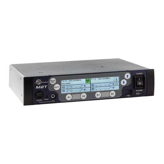
Power switch buttons previous screen Headphone Volume Headphone Jack USB Port IR Port Adjustment Channel Function Buttons/ Quick Sync M2T Back Panel Antenna Antenna Jack Dante Ports (optional) Jack XLR/TRS Combo Analog Ethernet Port Input Connectors Power Inlet LECTROSONICS, INC. -
Page 7: Operating Instructions
Power Screens When powering on the M2T, there are three screens IR (infrared) Port that appear in the following order, Duet, Lectrosonics, Settings, including frequency, name, limiter, mix mode, RF On/Off.: etc. can be transferred to and from the M2T transmitter via this port to an IR enabled receiver to simplify setup. -
Page 8: Lcd Menu Map
Use arrow keys Press SEL to DEFAULTS to select yes DEFAULTS BACK execute or no ABOUT No selections available; for ABOUT BACK information purposes only LINKS LINKS No selections available; use phone to scan QR code BACK for more information LECTROSONICS, INC. -
Page 9: Menu Item Descriptions
Digital IEM Transmitter Menu Item Descriptions Sync Settings Allows sending or retrieving setup data via IR port. RF Enable/Level Allows RF transmission to be turned on and off and set RF levels at 10, 25 or 50 mW. RF Tuning Allows manual selection of the operating frequency. -
Page 10: Audio Level/Trim
List or easily identify multiple M2T transmitters in a rack. • Use UP and DOWN Arrows to select letters and The headphone source can be selected here or on the MENU/SEL to set and move cursor. front panel, using the A1, A2, B1 or B2 Buttons. LECTROSONICS, INC. -
Page 11: Restore Defaults
Returns all settings to the factory defaults. About Displays general information about the M2T, including serial number, and the hardware, FPGA and microcontroller firmware versions. Links QR codes with links to the Lectrosonics website, the M2T User Manual online and YouTube video tutorials. Rio Rancho, NM... -
Page 12: Hardware Installation
(25990) Bracket rear tie • (25991) Bracket front tie • (27076) Rack flange bracket • (27082) Rack handle • (28885) (4) SCR10 cap screw • (35664) (4) Rubber foot large • (35959) Hole plug • (A500RA20) (2) Antenna LECTROSONICS, INC. - Page 13 Digital IEM Transmitter Rio Rancho, NM...
-
Page 14: Installing Two M2Ts Into A Single Rack Space
NOTE: The retaining nuts on the panel and tie brackets are “tensioning lock nut” types designed to prevent the screws from coming loose due to vibration. You will usually feel resistance as you tighten the screws - this is normal. LECTROSONICS, INC. - Page 15 Digital IEM Transmitter Rear tie bracket (Part #25990) Tensioning lock Front tie bracket nuts on the rear (Part #25991) side of the bracket 6. Install one side of the front tie bracket (Part #25991) Slide the other receiver over the tie bracket and in- into the side panel opening in one of the receivers.
-
Page 16: Wireless Designer Software And Usb Driver
Launch the installer and follow the screen prompts. When the installation is complete, the confirmation screen will appear. Click on Finish to complete the installation. I Agree on the EULA (end user license agreement) must be checked to continue the installation. LECTROSONICS, INC. -
Page 17: Software Installer
Digital IEM Transmitter Wireless Designer Click “Open Anyway”. Another warning dialog box opens, click “Open” to launch Wireless Designer. This only needs to be done once, Wireless Designer will Software and USB Driver launch normally thereafter. Software for Mac OS X Operating Systems Note: If Wireless Designer is already installed, ®... -
Page 18: Accessories
RMPM2T-1 Rack kit for mounting one M2T into a single rack space ARG 25; ARG 50; ARG 100 Antenna cable of Belden 9913F low-loss coax cable with BNC connectors at each end. Number speci- fies length in feet. LECTROSONICS, INC. -
Page 19: Specifications And Features
Digital IEM Transmitter Specifications and Features RF Power Output: • Two carriers; two audio channels each • Power adjustable on each carrier to 10, 25 or 50 mW Antenna Output: 2 x BNC sockets Operating Frequencies: 470.100 – 607.975 MHz Frequency Selection Steps: 25 kHz Frequency Stability: ±... -
Page 20: Service And Repair
LECTROSONICS’ Service Department is equipped and staffed to quickly repair your equipment. In warranty repairs are made at no charge in accordance with the terms of the warranty. Out-of-warranty repairs are charged at a modest flat rate plus parts and shipping. - Page 21 Digital IEM Transmitter Rio Rancho, NM...
- Page 22 LECTROSONICS, INC.
- Page 23 Digital IEM Transmitter ISEDC Notices: Per RSS-210 This device operates on a no-protection no-interference basis. Should the user seek to obtain protection from other radio services operating in the same TV bands, a radio licence is required. Please consult Industry Canada’s document CPC-2-1-28, Optional Licensing for Low-Power Radio Apparatus in the TV Bands, for details.
- Page 24 This warranty does not apply to used or demonstrator equipment. Should any defect develop, Lectrosonics, Inc. will, at our option, repair or replace any defective parts without charge for either parts or labor. If Lectrosonics, Inc. cannot correct the defect in your equipment, it will be replaced at no charge with a similar new item.
Need help?
Do you have a question about the M2T/ND and is the answer not in the manual?
Questions and answers