
Related Manuals for Leica RM2245


Summary of Contents for Leica RM2245
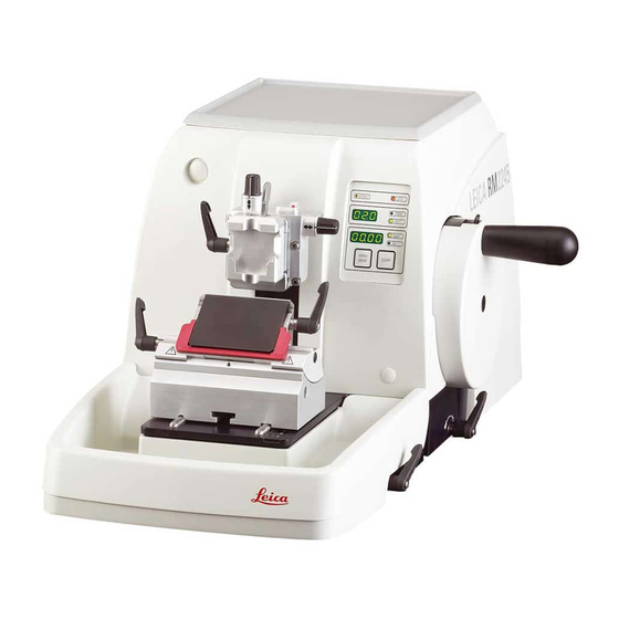
- Page 1 Rotary Microtome Instruction Manual Leica RM2245 V1.6 Rev B, English – 10/2009 Always keep this manual with the instrument. Read carefully before working with the instrument.
- Page 3 Leica reserves the right to change technical stand it following thorough investigation in this specifications as well as manufacturing proc- field.
-
Page 4: Table Of Contents
TABLE OF CONTENTS 1. Important Notes ............................6 Symbols in the text and their meanings ..................... 6 Qualification of personnel ..........................6 Intended use of instrument .......................... 6 Instrument type .............................. 6 2. Safety ................................7 Safety notes ..............................7 Warnings ................................. - Page 5 8. Cleaning and Maintenance ........................66 Cleaning the instrument ..........................66 Maintenance ..............................68 8.2.1 Replacing fuses ............................68 8.2.2 Maintenance instructions .......................... 69 8.2.3 Lubricating the instrument ......................... 70 9. Warranty and Service ..........................71 Peoples Republic of China ........................72 Leica RM2245...
-
Page 6: Important Notes
The Leica RM2245 is also suitable for IVD (in vitro diagnostics). Numbers in parentheses refer to item numbers in illustrations. -
Page 7: Safety
The protective devices on both instrument and accessories may neither be removed nor modified. Only service personnel qualified by Leica may repair the instrument and access the instrument’s internal components. 2.2 Warnings The safety devices installed in this instrument by the manufacturer only constitute the basis for accident prevention. - Page 8 Safety Warnings – Safety instructions / warning labels attached to the instrument • Safety instruction labels on the instrument marked with a warning triangle indicate that the correct operating instructions (as described in this manual) must be followed when operating or replacing the instrument component bearing the label.
- Page 9 • When using detergents please comply with the safety precautions of the manufacturer. • Turn the instrument off with the power switch and pull the power plug, before replacing the fuses! Only use fuses of the same specification! For fuse specifications, refer to chapter 3.3 – ‘Technical data’. Leica RM2245...
-
Page 10: Integrated Safety Devices
Safety 2.3 Integrated safety devices Locking the handwheel There are two ways of locking the handwheel (12): Using the lever (3) on the right side of the micro- tome base plate, the handwheel can be braked in almost any position. •... - Page 11 Knife holder E-TC the knife holder can occur. Clamping lever for the blade (10) at the right, clamping lever for the lateral displacement (11) at the left. Fig. 5 Leica RM2245...
-
Page 12: Instrument Components And Specifications
Instrument Components and Specifications 3.1 Overview – instrument components Leica RM2245 Instrument control panel Handwheel Directional Locking specimen holder mechanism fixture with quick clamping system Smooth-turning handwheel Lever of handwheel brake Knife guard on the knife holder Separate control panel... -
Page 13: Instrument Specifications
Main switch Power supply Fig. 7 3.2 Instrument specifications The Leica RM2245 is a semi-motorized rotary The retraction value can be selected as microtome with a light-action handwheel. required. The RM2245 supports two manual sectioning The motorized specimen head can be moved at modes: two speeds (300µm/s and 900µm/s). -
Page 14: Technical Data
Instrument Components and Specifications 3.3 Technical data General Approvals: The instrument-specific marks are located next to the identification label. Nominal supply voltages: 100 / 120 / 230 / 240 V AC ±10% Nominal frequency: 50/60 Hz Power draw: 70 VA Protective class : Power fuses: 2 x T 1.0 A UL listed... - Page 15 5 - 100 µm in 5 µm increments; can be turned off Electric coarse feed: 300 µm/s and 900 µm/s Repositioning of knife holder base north-south: ± 24 mm Maximum specimen size (W x H x D): 50 x 60 x 40 mm Specimen orientation horizontal: 8° vertical: 8° Leica RM2245...
-
Page 16: Startup
Startup 4.1 Standard delivery The Leica RM2245 standard delivery includes: 1 Leica RM2245 basic instrument, without orientation .... 14 0501 38178 1 handwheel, complete ..............14 0501 38181 1 external control panel ..............14 0501 38179 1 section waste tray ............... 14 0502 37931 1 set of power cables consisting of: 1 power cable for Germany ............ -
Page 17: Unpacking And Installation
3 3 3 3 3 4 4 4 4 4 5 5 5 5 5 4 4 4 4 4 4 4 4 4 4 4 4 4 4 4 Fig. 9 Leica RM2245... - Page 18 Startup 4.3 Unpacking and installation (cont.) • Take out the fixing module (5). To do so, hold it by the top edge of the module and in the recessed grip (6) and pull it out by pulling upwards. • Lift the instrument (7) by holding it by the base plate and under the instrument on 5 5 5 5 5 6 6 6 6 6...
-
Page 19: Assembling The Handwheel
(outlets) of the country of use. Do not use an extension cable! Checking the voltage Before connecting the instrument to the The Leica RM2245 can be connected to various power supply, be absolutely certain to electrical power grids (depending on voltage check that the voltage selector is set to... - Page 20 4. Startup Checking the voltage (continued) The voltage selector is located above the main power switch, on the left-rear side of the instru- ment (Fig. 7). The voltage setting is displayed in the viewing window (22). • Insert a small screwdriver into the cutout (25) and carefully pry out the insert.
-
Page 21: Switching On The Instrument
If the yellow LED in the LOCK field (4) of the control panel is lit, the mechanical handwheel lock or the handwheel brake (Item 3 in Fig. 2) is activated. The instrument cannot be started as long as the LED is lit. Leica RM2245... -
Page 22: Operation
5. Operation 5.1 Operating elements and their functions The operating functions of the microtome are divided between a control panel and a display unit on the microtome. A control panel on the instrument displays the current operating mode as well as various settings. All operating functions are centrally located in the separate control panel. -
Page 23: Control Panel
Coarse feed buttons Trimming mode: Coarse Coarse Coarse Coarse feed feed feed feed backward forward forward backward fast fast slow slow Sectioning mode: Multiple Multiple Single Single step step step step Fig. 15 backward forward forward backward Leica RM2245... -
Page 24: Display And Control Elements
5. Operation 5.1.3 Display and control elements Three-digit display This display is located both on the instrument and on the control panel. If the SECT LED is lit up, the display shows the section thickness setting in µm. If the TRIM LED is lit up, the display shows the trimming section thickness setting in µm. - Page 25 (ensure that version number 2.1 was displayed). This feature is only available in sectioning mode in version 2.1 or high- er. If you have an earlier software version, please contact Leica Service. Multiple Single...
- Page 26 5. Operation Forward coarse feed • Press the button to start the slow backwards movement. The travel continues as long as the button is held depressed. • Press the appropriate button to start a rapid or slow forward movement. The travel continues as long as the button is held depressed. •...
- Page 27 “OFF”. • To exit the retraction settings, press MENU MODE. When retraction is switched off, the specimen is not retracted. The yellow LED (4) of the RETRACT indicator does not light up. Leica RM2245...
- Page 28 5. Operation Indication of remaining horizontal feed The visible and audible remaining feed indica- tion feature informs the user during trimming Object head and sectioning when a remaining feed of ap- proximately 1 mm is available before the front limit is reached. The yellow LED (41) in the COARSE FEED button lights up from the beginning of the remaining feed.
- Page 29 (50 x 55 mm) is used, the speci- noticeable during turning. men orientation of 8° in north-south di- • To lock the current orientation, turn the rection is no longer possible. eccentric lever (29) backwards. The usable angle is only about 4° in this case. Leica RM2245...
- Page 30 5. Operation Fine adjustment of the force balance If another accessory of a different weight is mounted on the specimen head (33), you must check whether it is necessary to readjust the force balance. Checking the correct setting: • Attach the new accessory and clamp the specimen.
-
Page 31: Inserting The Knife Holder
4 (71) until the knife holder (57) can be moved. • Place the knife holder (57) with the under- side groove onto the T-piece (56) of the knife holder base (51). • To clamp, retighten the screw (58). Fig. 23 Leica RM2245... -
Page 32: Inserting The Universal Cassette Clamp
5. Operation 5.3 Inserting the universal cassette clamp There are two versions of the specimen holder, one with and one without specimen orientation, which are interchangeable. The object orientation allows for simple position correction of the specimen surface when the specimen is clamped into place. -
Page 33: Adjusting The Clearance Angle
Enlarged detail showing a clearance angle setting of 5°. recommended clearance 59.1 angle setting for knife holder E is approx. 5°. 59.2 • Hold down the knife holder in this position and retighten the screw (58) for clamping. Fig. 25 Leica RM2245... -
Page 34: Clamping The Specimen
5. Operation 5.5 Clamping the specimen Always clamp the specimen block BEFORE clamping the knife. Lock the handwheel and cover the knife edge with the knife guard prior to any manipulation of knife or specimen, prior to changing the specimen block and during all work breaks! •... - Page 35 (9) downward. Guide the brush with magnet to the blade and lift it upwards and out. Once the blade has been removed from the blade holder, it is disposed of into the dispenser container (underside, see image). Fig. 27 Leica RM2245...
-
Page 36: Cutting Into The Specimen (Trimming)
Operation 5.7 Cutting into the specimen (trimming) • Use the TRIM/SECT key to select the trim mode. • Set the desired trim section thickness. • Release the handwheel lock and the brake. • In TRIM mode, use the coarse feed buttons to move the specimen against the knife/blade. -
Page 37: Changing The Specimen Or Interrupting Sectioning
• Remove the specimen from the specimen clamp. • Push all section debris into the section waste tray and empty the tray. • Switch the instrument off at the main power switch. • Clean the instrument (see Chapter 8.1). Leica RM2245... -
Page 38: Optional Accessories
Optional accessories 6.1 Assembly for fixture for specimen clamps Depending upon the purchase order, the basic instrument is delivered with the directional or rigid fixture for specimen clamps which must be assembled first. All specimen clamps available as accessories can be used in both fixtures for specimen clamps. Before assembling the fixture for specimen clamps, activate the mechanical handwheel lock! 6.1.1 Rigid fixture for specimen clamps •... -
Page 39: Fine-Directional Fixture For Specimen Clamps
Allen key size 3 onto the specimen head. If the fine-directional fixture for speci- men clamps is not used, retain the base- plate and 4 screws (11) together with the fine-directional fixture for specimen clamps! Fig. 30 Leica RM2245... -
Page 40: Quick Clamping System
Optional accessories 6.1.4 Quick clamping system It is used as specimen holder for use with the fine-directional fixture for specimen clamps with zero point indicators or the directional fixture for specimen clamps. • Screw the 4 screws (13) into bore A with an Allen key size 2.5 and tighten them. -
Page 41: Specimen Clamps And Holders
(69) of the lower jaw (68). • Mount the specimen as required. • Turn the knurled screw (66) clockwise to move 70.1 the movable jaw with the vee insert upward against the fixed jaw to clamp the specimen Fig. 33 securely. Leica RM2245... -
Page 42: Foil Clamp Type 1
Optional accessories 6.2.3 Foil clamp type 1 Clamping of foil pieces • Move the movable jaw (74) to the right as The foil clamp type 1 is appropriate both for required by turning the setscrew with an clamping very small foil pieces and flat, angular Allen key size 4 (71). -
Page 43: Foil Clamp Type 2
(80) on the back of the foil clamp points to the right or left. • Turn the knurled screw (66) clockwise to clamp the foil clamp securely in the standard specimen clamp. Fig. 36 Leica RM2245... -
Page 44: Universal Cassette Clamp
Optional accessories 6.2.5 Universal cassette clamp The universal cassette clamps (UCC) are designed for horizontal or vertical clamping of all kinds of commercial cassettes. • Push the lever (60) forwards. • Mount the cassette (65) horizontally or verti- cally as required. •... -
Page 45: Super Mega-Cassette Clamp
If the directional fixture for specimen clamps is used with the rigid knife holder base, the orientation must be in position “0” and the cover for backlighting illumination must be detached. (Danger of collision if not observed!) NEVER use the super mega-cassette clamp with backlighting illumination! Leica RM2245... -
Page 46: Holder For Round Specimens
Optional accessories 6.2.7 Holder for round specimens The holder for round specimens is designed to accommodate cylindrical specimens. Inserts for specimens of 6, 15 and 25 mm diameter are available. • To mount the required insert (89.1-3) turn the 89.1 clamping ring (90) counterclockwise and remove it. -
Page 47: Knife Holder Base And Knife Holder
• Reposition the knife holder together with the knife holder base forward or backward as appropriate. • Secure the clamping mechanism by rotating the lever (50) clockwise. Fig. 42 Leica RM2245... -
Page 48: Knife Holder E/E-Tc
Prior to inserting the blade, both knife The knife holder E-TC is designed for the holder and knife holder base must have Leica TC-65 tungsten carbide blades. been installed on the instrument! Inserting the blades, knife holder E and E-TC Knife holder E-TC •... - Page 49 Leica Biosystems offers special prices for new clamp mounts in case of damages to the clamp mount after the warranty has expired. In this way, perfect function of the device can be ensured over the course of many years.
- Page 50 Optional accessories Knife holder E with water bath for narrow-band and broad-band blades Knife holder E with water bath is available for both narrow-band and broad-band blades. The knife guard on knife holder E consists of a red foldaway handle (9). To cover the cutting edge, fold the knife guard handle (9) upwards as illustrated in Figure.
-
Page 51: Knife Holder N/Nz
Knife holder N metal knives up to 16 cm in length. For holding convention- Knife pressure plate (56) for extreme al knives up to 16 cm in stability and full utilization of the length. knife blade. Fig. 48 Leica RM2245... - Page 52 Optional accessories Inserting the knife • Rotate the knurled nuts (48) on the right and left of the knife holder forward in opposite directions, lowering the knife support bar to the lowest possible position, thus ensuring that the knife edge will not be damaged when inserting the knife.
-
Page 53: Blades/Knives
Note: Knife case 14 0213 11140 included Order No........... 14 0216 07100 Profile Knife 12 cm profile c - steel Knife, 12 cm long, profile c Note: Knife case 14 0213 11140 included Order No..........14 0216 07092 Fig. 51 Leica RM2245... - Page 54 Optional accessories Knife 16 cm, profile d - steel Knife, 16 cm long, profile d Note: Knife case 14 0213 11140 included Order No..........14 0216 07132 Knife 12 cm, profile d - steel Knife, 12 cm long, profile d Note: Knife case 14 0213 11140 included Order No.
-
Page 55: Section Waste Tray
• Connect the plug (4) of the backlighting to the socket (5) on the microtome. The backlighting illuminates once the micro- tome is turned on with the power switch. NEVER use the backlighting illumination with the super mega-cassette clamp! Fig. 56 Leica RM2245... -
Page 56: Tray
6. Optional Accessories 6.7 Tray The tray is mounted on the hood of the micro- tome so that the small feet on the underside fit into the cutouts on the hood. It is for storage of the utensils used during sectioning as well as the sectioned specimens. -
Page 57: Universal Microscope Carrier
(c) Fig. 59 3 - Horizontal arm with cross-member (d) and support ring (e) 4 - Support plate, large (for RM2235, RM2245 and RM2255) 5 - Support plate, small (for RM2265) 6 - Allen key size 3 7 - 4 countersunk screws to install support plate 8 - Allen key size 8 Fig. - Page 58 Optional accessories 2. Attach vertical column • Insert the cap screw (b) into the hole of the baseplate from below. Place the lock washer (c) on the cap screw from above. • Thread the silver vertical column (2) onto the baseplate from above and tighten with the Al- Fig.
-
Page 59: Magnifying Lens
6. Optional Accessories 6.10 Magnifying lens The magnifying lens provides a 2x magnification and can be used with all Leica 2200 series rotary microtomes. • Open the screw (3) on the horizontal arm of the microscope carrier in a counterclock- wise direction. -
Page 60: Cold Light Source
(7). • Remove the protective caps (8) and align the light guide with the specimen. Fig. 69 Fig. 71, Leica rotary microtome with installed optional Fig. 70 accessories: magnifying lens and fiber-optic light guide Instruction manual V 1.6 – 10/2009... -
Page 61: Ordering Information
Universal cassette clamp, with adapter (silver) ............. 14 0502 37999 Universal cassette clamp - ice-cooled ................14 0502 37793 Megaclamp assembly RM22xx, silver ................14 0502 38967 Foil clamp - type 1, black ....................14 0402 09307 Foil clamp - type 2, black ....................14 0402 26922 Leica RM2245... - Page 62 Special wrench f. EM holder .................... 14 0356 10869 Universal microscope carrier, complete ................ 14 0502 40580 Magnifying lens assembly ....................14 0502 42790 Cold light sources Leica CLS 100X, 100-120V/50-60Hz ................14 0502 30214 Leica CLS 100X, 230V/50-60Hz................14 0502 30215 Leica CLS 100X, 240V/50-60Hz................
-
Page 63: Troubleshooting
• Proceed as described above. • Work normally after checking the settings. • Have the battery replaced by Leica service as soon as possible. LEDs (40), (41) in the coarse feed buttons are lit at the same time. This indicates a defect in the detection of the STOP and HOME positions of the specimen head. -
Page 64: Malfunctions, Possible Causes And Troubleshooting
Following is a list of the most common problems which can arise while working with the instru- ment, along with possible causes and troubleshooting procedures. If the malfunction cannot be remedied with any of the options listed in the table, or the problem occurs repeatedly, inform the Leica Service Support immediately. Problem Possible cause Corrective action 1. -
Page 65: Possible Faults
If necessary, tighten the levers and screws. 5. High blade consumption • Too great of a sectioning force • Adjust the sectioning speed was applied. and/or section thickness when sectioning. Select a thinner section. Leica RM2245... -
Page 66: Cleaning And Maintenance
8. Cleaning and Maintenance 8.1 Cleaning the instrument Always remove the knife / blade before detaching the knife holder from the instrument. Always put the knives back into the knife case when not in use! Never place a knife anywhere with the cutting edge facing upwards and never try to catch a falling knife! When using cleaners, comply with the safety instructions of the manufacturer and the labor-safety regulations of your laboratory! - Page 67 Chapter 8.2.3). • When installing the pressure plate (83), en- sure that the upper edge is parallel to and level with the rear edge of the knife holder base (86) (see also Fig. 39, Page 48). Fig. 73 Leica RM2245...
-
Page 68: Maintenance
Cleaning and Maintenance Universal cassette clamp • Detach cassette clamp (13) for a thorough cleaning, removing all paraffin residues. • For cleaning, do not use xylene. Use xylene substitutes or paraffin removers such as “Para Gard.” • The cassette clamp (13) can also be placed in an oven heated to a maximum of 65 °C, until the liquid wax escapes. -
Page 69: Maintenance Instructions
TRIM/SECT button is pressed ↓ ↓ ↓ ↓ ↓ (switching between trimming and sectioning mode). This is a reminder that the instrument must be inspected by an author- ized Leica service technician, regardless of how heavily the instrument has been used. Leica RM2245... -
Page 70: Lubricating The Instrument
Cleaning and Maintenance 8.2.3 Lubricating the instrument Once a month, lubricate the following parts with the included drive parts oil No. 405 (1 - 2 drops are enough). Instrument and specimen holder: • The clamping key (95) of the quick clamping system. -
Page 71: Warranty And Service
Leica Biosystems Nussloch GmbH guarantees that the contractual prod- uct delivered has been subjected to a comprehensive quality control pro- cedure based on the Leica in-house testing standards, and that the prod- uct is faultless and complies with all technical specifications and/or agreed characteristics warranted. -
Page 72: Peoples Republic Of China
Peoples Republic of China Instruction manual V 1.6 – 10/2009...
Need help?
Do you have a question about the RM2245 and is the answer not in the manual?
Questions and answers