
Related Manuals for Oliver 10060.001


Summary of Contents for Oliver 10060.001
-
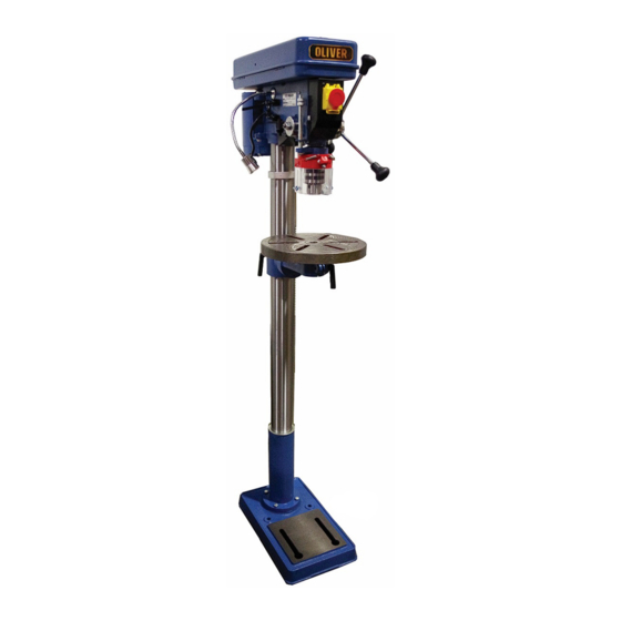
Page 1: Drill Press
10060.001 & 10061.0001 Drill Press Owner’s Manual Oliver Machinery M-10060/61 11/2018 Seattle, WA Copyright 2003-2018 info@olivermachinery.net www.olivermachinery.net... - Page 3 To help ensure safe operation, please take a moment to learn the machine’s applications and limitations, as well as potential hazards. Oliver Machinery disclaims any real or implied warranty and holds itself harmless for any injury that may result from the improper use of its equipment.
- Page 4 Never remove the third prong. 23. Do not use this drill press for other than its intended use. If used for other purposes, Oliver Machinery disclaims any real implied warranty and holds itself harmless for any injury, which may result from that use.
-
Page 5: Screw
EXTENSION CORDS Oliver Machinery does not recommend the use of an extension cord with your machine. However, if you must use an extension cord, make sure it has an amperage suitable for the rating on the motor ID nameplate. -
Page 6: Helical Gear
Lay out the parts in an unobstructed area, some pieces such as the head will need two people to safely move. • If you have any questions during assembly, please contact Oliver Machinery at 800-559-5065 or email at info@olivermachinery.net. Assembling the Drill Press 1. -
Page 7: Feed Handle
Installing the Drill Chuck Guard 1. Loosen the clamp screw on the CHUCK GUARD (87). 2. Slide the chuck guard onto the shoulder of the SPINDLE (51). 3. Make sure it is equally in place and tighten the clamp screw. Installing the Drill Chuck 1. -
Page 8: Lock Screw
Table Swing Position 1. Loosen the CLAMP LEVER (11). 2. Swing TABLE (17) to the desired position. 3. Tighten the CLAMP LEVER (11). 4. Align center hole in table to drill bit position to avoid drilling into the table. 5. For large pieces the BASE (1B) can be used as the table. Changing Speeds 1. -
Page 9: Depth Stop Adjustment
Depth Stop Adjustment 1. Set the bottom DEPTH STOP LOCK NUT (85) to the desired depth setting. 2. Tighten the second lock nut against the first nut to secure it in position. Laser Adjustment 1. Using a small bit (1/16” or less) drill a hole in a scrap piece of wood the same thickness as your workpiece. - Page 11 1 0 0 6 0 . 0 0 1 / 1 0 0 6 1 . 0 0 1...
- Page 12 PART LIST FOR 10060.001 and 10061.001 PART NO. DESCRIPTION 10061-1 BASE FLOOR MODEL 10060-1 BASE BENCH MODEL 10061-2 WASHER 10061-3 BOLT FLOOR MODEL 10060-3 BOLT BENCH MODEL 10061-4 BASE FLANGE FLOOR MODEL 10060-4 BASE FLANGE BENCH MODEL 10061-5 SCREW 10061-6...
- Page 13 PART LIST FOR 10060.001 and 10061.001 PART NO. DESCRIPTION 10061-40 POWER CORD w/MOLDED PLUG 40-1 10061-40-1 MOTOR TO SWITCH CORD 10061-41 SNAP RING 10061-42 DRIVER INSERT BB-6203 6203 BALL BEARING 10061-44 SNAP RING BB-6201 6201 BALL BEARING 10061-46 QUILL GASKET...
- Page 14 PART LIST FOR 10060.001 and 10061.001 PART NO. DESCRIPTION 10061-82 10061-83 SET SCREW 10061-84 DEPTH STOP ROD 10061-85 DEPTH STOP LOCK NUT 10061-86 DEPTH STOP SUPPORT 10061-87 CHUCK GUARD 10061-88 LASER TRANSFORMER 10061-89 LASER SWITCH 10061-90 SCREW 10061-91 LED LIGHT...
Need help?
Do you have a question about the 10060.001 and is the answer not in the manual?
Questions and answers