
Subscribe to Our Youtube Channel
Related Manuals for Michell Instruments Easidew Online


Summary of Contents for Michell Instruments Easidew Online
- Page 1 Easidew Online Dew-Point Hygrometer User’s Manual 97094NA Issue 16.2, December 2010 Michell Instruments...
- Page 2 Inside front cover (blank)
- Page 3 Easidew Online © 2010 Michell Instruments This document is the property of Michell Instruments Ltd. and may not be copied or otherwise reproduced, communicated in any way to third parties, nor stored in any Data Processing System without the express written authorization of Michell Instruments Ltd.
-
Page 4: Table Of Contents
Easidew Online User’s Manual Contents Safety ..............................vi Electrical Safety .........................vi Pressure Safety .........................vi Toxic Materials ..........................vi Repair and Maintenance......................vi Calibration ..........................vi Safety Conformity ........................vi EC Declaration of Conformity......................vii Abbreviations ..........................viii Recycling Policy ..........................ix WEEE and RoHS Compliance ......................x Calibration Facilities ........................... - Page 5 General Operational Guidelines ..................41 Maintenance and Calibration ..................43 5.2.1 Clean Process Indicator .....................43 Figures Figure 1.1 Easidew Online process indicator and transmitter ............1 Figure 2.1 Process indicator panel layout ..................2 Figure 2.2 Flowchart Example ...................... 7 Figure 3.1 Unpacking method ......................
-
Page 6: Safety
The recommended calibration interval for this instrument is 12 months unless it is to be used in a mission- critical application or in a dirty or contaminated environment in which case the calibration interval should be reduced accordingly. The instrument should be returned to the manufacturer, Michell Instruments Ltd., or one of their accredited service agents for re-calibration. -
Page 7: Ec Declaration Of Conformity
Easidew Online User’s Manual EC Declaration of Conformity EC Declaration of Conformity Michell Instruments Limited 48 Lancaster Way Business Park Ely, Cambridgeshire CB6 3NW. UK. declare under our sole responsibility that the product Easidew On-Line Hygrometer to which this declaration relates is in conformity with the following standards... -
Page 8: Abbreviations
Easidew Online User’s Manual Abbreviations The following abbreviations are used in this Manual: alternating current pressure unit (atmosphere) pressure unit (=100 kP or 0.987 atm) bara bar absolute ºC degrees Celsius ºF degrees Fahrenheit direct current foot (feet) gram(s) Hertz “... -
Page 9: Recycling Policy
Recycling Policy Michell Instruments is concerned with the protection of the environment. It is our commitment to reduce and eliminate from our operations, wherever possible, the use of substances which may be harmful to the environment. -
Page 10: Weee And Rohs Compliance
June 2010 Calibration Facilities Michell Instruments’ calibration facilities are among the most sophisticated in the world and have been recognized for their excellence. Traceability to the National Physical Laboratory (NPL) UK is achieved through our UKAS Accreditation (Number 0179). -
Page 11: Warranty
All warranty services are provided on a return to base basis. Any transportation costs for the return of a warranty claim shall reside with the Customer. Return Policy If a Michell Instruments’ product malfunctions within the warranty period, the following procedure must be completed: Notify a Michell Instruments’ distributor, giving full details of the problem, the model variant and the serial number of the product. -
Page 12: Introduction
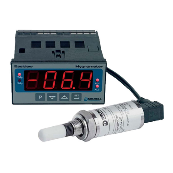
Easidew Online User’s Manual INTRODUCTION The Easidew Online dew-point hygrometer is an instrument designed for the continuous online measurement of moisture content in non-corrosive gases, over an operational range of -100 to +20ºCdp (-148 to +68ºFdp). The system comprises a programmable process indicator configured to accept a 4-20 mA current loop signal from an impedance-type dew-point temperature measurement transmitter. The span of the process indicator is set to cover the dew-point range -100 to +20ºCdp (-148 to +68ºFdp) at operating pressures up to 45 MPa... -
Page 13: Description
Easidew Online User’s Manual DESCRIPTION The controls and indicators associated with the Easidew Online are located on the front panel of the process indicator. Connections to the Easidew dew-point transmitter, the RS232 communications port and the external power supply are all made to the rear panel of the process indicator (refer to Section 3). -
Page 14: Table 2.1 Process Indicator Front Panel Controls And Indicators
Easidew Online User’s Manual Item Description ºFdp When illuminated, this LED indicates that the displayed dew-point reading is in degrees Fahrenheit. Note: If neither the ºFdp or ºCdp LED is lit, ppm is selected. ºCdp When illuminated, this LED indicates that the displayed dew-point reading is in degrees Celsius. -
Page 15: Function Keys
Easidew Online User’s Manual Function Keys The four function keys, located below the display, are used for setting up the process indicator. The following set-up functions are covered in Section 4 of this Manual: • Reversal of alarm level switching logic •... -
Page 16: Process Indicator Menu Structure
Process Indicator Menu Structure Once the Easidew Online is set-up it should not require much adjustment. The dew-point transmitter is supplied calibrated over the range -100 to +20ºCdp (-148 to +68ºFdp) and has a linear output in the range of 4-20 mA (corresponding to -100ºCdp (-148ºFdp) and +20ºCdp (+68ºFdp) respectively). -
Page 17: Flowchart Reading Method
Easidew Online User’s Manual Symbol Description Display reading / Indication Outline is shown as solid green if the display is static Display reading / Indication Outline is shown as solid red if the display is flashing Display Outline is shown as red, hatched to indicate that the display is alternately flashing between the two indicated values Indicates the requirement to press the ‘... -
Page 18: Flowchart Example
Easidew Online User’s Manual 2.3.2 Flowchart Example The following is a flowchart example showing Main display the set-up of alarm levels. For actual set-up instructions see Section 4.3.2. Set x2 for Alarm 2 only The alarm set-point levels are set-up from the... -
Page 19: Installation
Easidew Online User’s Manual INSTALLATION Safety It is essential that the connection of electrical and gas supplies to this instrument be undertaken by competent personnel Unpacking the Instrument The Easidew instruments and accessories are packed into a box and the method of unpacking is shown as follows in Figure 3.1:... -
Page 20: Figure 3.2 Transmitter Unpacking Method
Easidew Online User’s Manual Unpack the dew-point transmitter box as follows (see Figure 3.2). Figure 3.2 Transmitter unpacking method Remove the cap (1) from the packing tube (6). Remove the cover (2). Remove the transmitter from the tube, complete with the body cover (4) and tip cover (5). -
Page 21: Figure 3.4 Process Indicator
Easidew Online User’s Manual The process indicator (3) is packed, together with its fixing clamps (1) as shown in Figure 3.4. Figure 3.4 Process indicator Remove the items from the box but retain the packing for future use. 97094NA Issue 16.2, December 2010 Michell Instruments... -
Page 22: Easidew Components
Easidew Online User’s Manual Easidew Components The Easidew Online dew-point hygrometer and its accessories are shown in Figure 3.5 . Figure 3.5 Easidew Online components Please check that all these components are present after unpacking. Report any shortages immediately. Process indicator clamps (2 off) -
Page 23: Operational Requirements
Easidew Online User’s Manual Operational Requirements The following operational requirements are required: 3.4.1 Environmental Requirements – Process Indicator Operating temperature range: 0ºC to +50ºC (+32ºF to +122ºF) Humidity: 90% RH (non-condensing) Altitude: Up to 2000 m 3.4.2 Electrical Requirements Supply voltage:... -
Page 24: Figure 3.6 Mounting The Process Indicator
Easidew Online User’s Manual Figure 3.6 Mounting the process indicator Michell Instruments 97094NA Issue 16.2, December 2010... -
Page 25: Electrical Connections
Easidew Online User’s Manual Electrical Connections Electrical connections to the Easidew Online system are as follows: • AC power supply, 100 V to 240 V AC (+10%, -15%), 50/60 Hz, 6 VA. A low voltage (24 V DC) option is also available. -
Page 26: Ac Power Supply Input
Easidew Online User’s Manual 3.6.1 AC Power Supply Input It is essential that the connection of electrical supplies to this instrument be undertaken by competent personnel Connect the AC power supply to the process indicator (1) as shown in Figure 3.7 . Refer also to Table 3.1 which gives a summary of all the connections to the rear panel of the process indicator. -
Page 27: Preliminary System Test
Easidew Online User’s Manual 3.6.2 Preliminary System Test Before wiring the external signal outputs and the transmitter, perform a system check as follows: Switch off and disconnect the power supply. Connect to an AC supply and switch the supply ON. The process indicator display should come on. -
Page 28: Dc Power Supply Input (Optional)
Easidew Online User’s Manual 3.6.3 DC Power Supply Input (Optional) Connect the DC power supply to the process indicator (1) as shown in Figure 3.8 . Refer also to Table 3.1 which gives a summary of all the connections to the rear panel of the process indicator. -
Page 29: Transmitter Connections
Easidew Online User’s Manual 3.6.4 Transmitter Connections Connect the transmitter cable to the process indicator (1) as shown in Figure 3.9. 1 0 1 2 2 2 0 2 1 1 9 2 7 1 8 1 6 1 1 4 1... -
Page 30: Signal Output Connections
Easidew Online User’s Manual Signal Output Connections The Easidew Online system has three signal outputs, Alarm 1 (ALr1), Alarm 2 (ALr2) and the re-transmitted input signal (4-20 mA or 0-20 mA current loop signal depending upon instrument configuration). Figure 3.10 shows the relevant rear panel connections. Table 3.1 shows a summary of all the electrical connections to the process indicator. -
Page 31: Table 3.1 Summary Of Electrical Connections
Easidew Online User’s Manual Terminal Wire Color Signal Supply Information Blue 0 V (GND) Green 4-20 mA loop current Default 4-20 mA Transmitter loop supply (+ve) +24 V DC w.r.t. terminal 1 User defined ALR2 (normally closed) User defined ALR2 (normally open) -
Page 32: Mounting The Sample Block And Transmitter
Easidew Online User’s Manual Mounting the Sample Block and Transmitter 3.8.1 Sample Block Gas Connections Sample gas connections are made to the Gas In and Gas Out ports on the sample block see Figure 3.11. Either port on the sample block may be used as the Gas Input port (i.e. for connection purposes the ports are interchangeable). - Page 33 Easidew Online User’s Manual NOTE: Threads Pass the stainless steel tubing (1) through the locking nut (2). towards the gas port. Fit the back ferrule (3) over the stainless steel tubing (1) with the bevelled end facing the back of the front ferrule (4).
-
Page 34: Transmitter Mounting - Sample Block
Easidew Online User’s Manual 3.8.2 Transmitter Mounting - Sample Block The following procedure must be carried out by a qualified installation engineer. To mount the transmitter into the sensor block (preferred method), proceed as follows, refer to Figure 3.12. Remove the blue protective cover (2) from the tip of the transmitter (1). -
Page 35: Figure 3.12 Transmitter Mounting - Sensor Block
Easidew Online User’s Manual Figure 3.12 Transmitter mounting - sensor block 97094NA Issue 16.2, December 2010 Michell Instruments... -
Page 36: Transmitter Mounting - Direct Pipeline Connection
Easidew Online User’s Manual 3.8.3 Transmitter Mounting - Direct Pipeline Connection The transmitter may be directly mounted into a pipe or duct as shown in Figure 3.13. CAUTION: Do not mount the transmitter too close to the bottom of a bend where any condensate in the pipeline might collect and saturate the probe. -
Page 37: Operation
The instrument must also have been installed as detailed in Section 3 and connected to a sample gas supply that is representative of the process being monitored. General Operational Information Operation of the Easidew Online hygrometer is completely automatic and once set-up requires little or no operator intervention. The dew-point transmitter is designed to operate in a flowing gas stream of between 1 and 5 l/min (2.1 and 10.6 SCFH) at operating pressures up to a maximum of 45 MPa (450 barg / 6500 PSI). -
Page 38: Preparation For Operation
Easidew Online User’s Manual Preparation For Operation Prior to operation, the instrument must be connected to the correct electrical power supply and the relevant analog and alarm outputs connected to external systems as required and as described in Section 3. -
Page 39: System Alarms
Easidew Online User’s Manual 4.3. System Alarms The Easidew Online system has two alarm outputs. As supplied, the default alarm set-points and the alarm switching logic are as follows (the default temperature units are degrees Celsius): AL1) set to -20ºCdp •... -
Page 40: Reversal Of Default Alarm Switching Logic
Easidew Online User’s Manual 4.3.1 Reversal of Default Alarm Switching Logic As described in Section 4.3, the switching logic for the alarm channels may, if required, be individually reversed. Starting at the default state, the method of reversing the switching logic for both alarms is as follows: Figure 4.2 shows the operational key sequence. -
Page 41: Figure 4.2 Change Alarm Switching Logic
Easidew Online User’s Manual Main Display (Change Alarm 2 Switching Logic) Main Main Display Display Figure 4.2 Change alarm switching logic 97094NA Issue 16.2, December 2010 Michell Instruments... -
Page 42: Set-Up Alarm Levels
Easidew Online User’s Manual 4.3.2 Set-up Alarm Levels The alarm set-point levels are set-up from the Main display program menu as follows (to exit to the main display without saving any new settings press the ‘ ’ key): Set x2 for Alarm 2 Only Figure 4.3 shows the operational key sequence. -
Page 43: Configure Analog Output Current Loop
Easidew Online User’s Manual 4.3.3 Configure Analog Output Current Loop The Easidew Online is provided with an analog current loop output module which buffers and re-transmits the current loop input signal from the dew-point transmitter. By default, the re-transmission output is set as a 4-20 mA current loop (to exactly follow the input signal, i.e. -
Page 44: Change Dew-Point Temperature Range
Easidew Online User’s Manual 4.4. Change Dew-Point Temperature Range The default temperature unit for the Easidew Online instrument is degrees Celsius. This is indicated by the º LED indicator. The default settings associated with this temperature scale are as follows: •... -
Page 45: Span And Unit Settings
Easidew Online User’s Manual 4.4.1 Span and Unit Settings To change the span and unit settings, proceed Main Display (°C) as follows. Figure 4.5 shows the operational key sequence. Press the ‘ ’ key once, the display will tECH read ‘... -
Page 46: Configure Alarm Set-Point Limits
Easidew Online User’s Manual 4.4.2 Configure Alarm Set-Point Limits Main display The following procedure is used to set limits to which the alarm levels can be set (usually after re-configuring the instrument’s range for Fahrenheit readings). Figure 4.6 shows the operational key sequence. -
Page 47: Change Scale Units (To Ppm )
Figure 4.7 shows the operational key sequence. Note: The dew-point transmitter must first be programmed to provide an output proportional to by using the Michell application software. Contact Michell Instruments for information (for contact details see Appendix E). Press the ‘... -
Page 48: Figure 4.7 Set-Up Process Indicator (To Read Ppm )
Easidew Online User’s Manual Main Display, e.g. °C Main Display, ppm(v) Figure 4.7 Set-up process indicator (to read ppm Michell Instruments 97094NA Issue 16.2, December 2010... -
Page 49: Set-Up Communications Parameters
Easidew Online User’s Manual Set-Up Communications Parameters The default parameters for the Easidew Online instrument are as follows: Default Address = 1, Baud rate = 9600, Parity = None, Stop bits = 1 To change these parameters, proceed as follows: Figure 4.8 shows the operational key sequence. -
Page 50: Set-Up Data Communications Parameters
Easidew Online User’s Manual Main display Set Parity 0 = None 1 = Odd 2 = Even Set number of Set Address stop bits Range between 0 = 1 stop bit 0001 and 0247 1 = 2 stop bits Set baud Main Display (°F) -
Page 51: Good Measurement Practice
The transmitter is designed for operation with sample gas flow rates of 1 to 10 l/min (2.1 to 22.2 SCFH). Ideally, the flow rate should be set-up between 4 and 6 l/min (8.5 and 12.7 SCFH), (5 l/min (10.6 SCFH) is the recommended optimum. Flow regulation is not provided within the Easidew Online system. Sample gas flow must therefore be regulated outside the instrument, on the input side of the sample block by means of a precision needle valve. Always use high quality valve gear, coupling connections and pipework. -
Page 52: General Operational Guidelines
Easidew Online User’s Manual General Operational Guidelines General guidelines to be followed when setting-up a sampling system are as follows: • Be Sure the Sample is Representative of the Gas Under Test The sample point should be as close to the critical measurement point as possible. Also, never sample from the bottom of a pipe as entrained liquids may be drawn into the sensing element. - Page 53 Easidew Online User’s Manual • Avoid the use of too many Tee pieces, in-line couplings or other unnecessary pipework Sample pipework should, ideally, be specially designed for each application rather than adapted from that previously installed for another application. Dead space in sample lines increases response time by holding water molecules which are more slowly released to the passing gas sample.
-
Page 54: Maintenance And Calibration
National Physical Laboratory (UK) or the National Institute of Standards and Technology (USA). The Easidew transmitter can be returned to Michell Instruments either directly or via the authorized distributor, for calibration at 13 points across the range -100 to +20ºCdp (-148 to +68°Fdp). - Page 55 Easidew Online User’s Manual Appendix A Technical Specifications 97094NA Issue 16.2, December 2010 Michell Instruments...
-
Page 56: Appendix A Technical Specifications
Easidew Online User’s Manual Appendix A Technical Specifications Monitor Equipment Use Process indicator – dew-point measurement Housing & Mounting 48 x 96 x 86 mm (1.9 x 3.8 x 3.4”) Horizontal, DIN 43700 Plastic housing for panel mounting. Panel cut out is 46 x 92 mm (1.8 x 3.6”) -
Page 57: Appendix Bul Certification
Easidew Online User’s Manual Appendix B UL Certification 97094NA Issue 16.2, December 2010 Michell Instruments... - Page 58 Easidew Online User’s Manual Appendix B UL Certification Below are listed the requirements of UL Certification: Standards: 61010-1, edition, 2005-07-22 (Electrical Equipment for Measurement, control, and laboratory use: Part 1: General requirements) CAN/CSA-C22.2 No. 61010-1 2nd edition, 2004,-07, (Electrical Equipment for Measurement, control, and laboratory use: Part 1:...
- Page 59 Easidew Online User’s Manual Appendix C Fahrenheit or Celsius 97094NA Issue 16.2, December 2010 Michell Instruments...
-
Page 60: Appendix C Fahrenheit Or Celsius
Easidew Online User’s Manual Appendix C Fahrenheit or Celsius Ranging of the monitor is achieved by using the following procedure. (The figures in brackets are the °F equivalents of the °C values). tECH Press the ‘ ’ key and the display will show ‘... - Page 61 Easidew Online User’s Manual Appendix D RS232 Data Communications Port Connections (Optional) 97094NA Issue 16.2, December 2010 Michell Instruments...
-
Page 62: Figure A.1 Rs232 Connections
Appendix D RS232 Data Communications Port Connections (Optional) The Easidew Online instrument has an RS232 port, situated on the rear panel of the process indicator. This port enables remote access to the instrument’s configuration and the indicated dew-point temperature. The method of connection is shown in Figure A.1 and the following items will be required (these are not supplied with the Easidew system): •... - Page 63 Easidew Online User’s Manual Appendix E List of Worldwide Michell Instruments’ Offices 97094NA Issue 16.2, December 2010 Michell Instruments...
-
Page 64: Appendix E List Of Worldwide Michell Instruments' Offices
Easidew Online User’s Manual Appendix E List of Worldwide Michell Instruments’ Offices Benelux Asia Michell Instruments Benelux BV Michell Asia Krombraak 11 PO Box 3149 4906 CR Oosterhout Joondalup The Netherlands WA 6027 Tel: +31 162 680 471 Australia Fax:... - Page 65 http://www.michell.com...
Need help?
Do you have a question about the Easidew Online and is the answer not in the manual?
Questions and answers