Sign In
Upload
Manuals
Brands
Michell Instruments Manuals
Measuring Instruments
Easidew Online
Michell Instruments Easidew Online Manuals
Manuals and User Guides for Michell Instruments Easidew Online. We have
3
Michell Instruments Easidew Online manuals available for free PDF download: User Manual
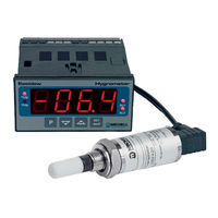
Michell Instruments Easidew Online User Manual (68 pages)
Dew-Point Hygrometer
Brand:
Michell Instruments
| Category:
Measuring Instruments
| Size: 1 MB
Table of Contents
Table of Contents
4
Safety
7
Electrical Safety
7
Pressure Safety
7
Toxic Materials
7
Repair and Maintenance
7
Calibration
7
Safety Conformity
7
Abbreviations
8
Warnings
8
1 Introduction
9
Figure 1 Easidew Online Monitor and Transmitter
9
Features
10
2 Installation
11
Unpacking the Instrument
11
Figure 2 Unpacking Method
11
Unpacking the Easidew Transmitter
12
Unpacking the Monitor
12
Figure 3 Transmitter Unpacking Method
12
Figure 4 Monitor Unpacking Method
12
Accessories Pack
13
Easidew Online Components
13
Figure 5 Accessories Pack
13
Figure 6 Easidew Online Components
13
Easidew Transmitter
14
Figure 7 Easidew Transmitter
14
Monitor
15
Monitor Panel Layout
15
Figure 8 Monitor Panel Layout
15
Table 1 Monitor Front Panel Controls and Indicators
16
Function Keys
17
Table 2 Function Keys
17
Mounting the Monitor
18
Figure 9 Mounting the Monitor
18
Electrical Connections
19
AC Power Supply Input
20
Figure 10 AC Power Supply Connections
20
DC Power Supply Input (Optional)
21
Figure 11 DC Power Supply Connections
21
Preliminary System Test
22
Mounting the Sample Block and Transmitter
22
Sample Block Gas Connections
22
Figure 12 Sample Block Gas Connections
23
Preparation of the Transmitter Cable
24
Figure 13 Connector Terminal Block Removal
24
Figure 14 Wiring Connections
24
Cable Connection
25
Electrical Schematic
25
Figure 15 Connector Installation
25
Figure 16 2-Wire Connection Diagram
25
2.12.1 Electrical Boundaries
26
Transmitter Mounting
26
Figure 17 Maximum Load of Easidew - Including Cable Resistance
26
Transmitter Mounting - Sample Block (Optional)
27
Figure 18 Transmitter Mounting - Sensor Block
27
2.13.2 Transmitter Mounting - Direct Pipeline Connection
28
Figure 19 Transmitter Mounting - Pipe or Duct
28
2.13.3 Transmitter Mounting - with Additional Process Connection Adapter
29
Figure 20 Transmitter Mounting with Adapter
29
2.13.4 Monitor Connection
30
Figure 21 Transmitter Connections
30
Signal Output Connections
31
Figure 22 Monitor Rear Panel Connections
31
Table 3 Summary of Electrical Connections
32
3 Operation
33
General Operational Information
33
Preparation for Operation
34
First Time Operation
34
Figure 23 Typical Display
34
System Alarms
35
Alarm Switching Logic (Default)
35
Reversal of Alarm Switching Logic
36
Figure 24 Change Alarm Switching Logic
37
Alarm Level Set-Up
38
Figure 25 Set-Up Alarm Levels
38
Re-Transmitted Output Current Range Set-Up
39
Figure 26 Confi Gure Analog Output
39
Operating Temperature / Ppm Range
40
Temperature Range Default
40
Span and Unit Settings
41
Figure 27 Span and Unit Settings
41
Alarm Set-Point Limit Confi Guration
42
Figure 28 Set-Up Alarm Set-Point Limits
42
Scale Units to Ppm Set-Up
43
Monitor Limits When Unit Scaled to Ppm
44
Figure 29 Set-Up Monitor (to Read Ppm )
44
Digital Communication Parameters Set-Up
45
Figure 30 Set-Up Data Communications Parameters
46
Monitor - Reading the Displayed Value Using Modbus RTU over RS232
47
4 Good Measurement Practice
48
General Operational Guidelines
49
Figure 31 Installation Location
49
Figure 32 Indication of Dead Space
49
Maintenance and Calibration
50
Clean Monitor
50
Fault Conditions
51
Figure 33 Dimensions
53
Technical Specifi Cations
53
Appendix A Technical Specifi Cations
53
Dimensions
55
A.1 Dimensions
55
Figure 34 RS232 Connections
57
Appendix A Technical Specifi Cations
57
Appendix Brs232 Data Communications Port Connections (Optional)
57
Appendix C EC Declaration of Conformity
58
EC Declaration of Conformity
59
Appendix D Quality, Recycling & Warranty Information
61
Pressure Equipment Directive (PED) 97/23/EC
61
Recycling Policy
61
WEEE Compliance
61
Rohs2 Compliance
62
Warranty
62
D.4 Rohs2 Compliance
62
REACH Compliance
63
Calibration Facilities
63
D.6 REACH Compliance
63
Return Policy
64
Manufacturing Quality
64
D.8 Return Policy
64
Appendix E Return Document & Decontamination Declaration
66
Advertisement
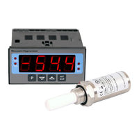
Michell Instruments Easidew Online User Manual (60 pages)
Online Dew-Point Hygrometer
Brand:
Michell Instruments
| Category:
Measuring Instruments
| Size: 3 MB
Table of Contents
Table of Contents
4
Safety
7
Electrical Safety
7
Pressure Safety
7
Toxic Materials
7
Repair and Maintenance
7
Calibration
7
Safety Conformity
7
Abbreviations
8
Warnings
8
1 Introduction
9
Figure 1 SF82 Online Monitor and Transmitter
9
Features
10
2 Installation
11
Unpacking the Instrument
11
Figure 2 Unpacking Method
11
Unpacking the SF82 Transmitter
12
Unpacking the Monitor
12
Figure 3 Transmitter Unpacking Method
12
Figure 4 Monitor Unpacking Method
12
Accessories Pack
13
SF82 Online Components
13
Figure 5 Accessories Pack
13
Figure 6 SF82 Online Components
13
Monitor
14
Fault Conditions
14
Figure 7 Monitor Panel Layout
14
Monitor Controls and Indicators
15
Table 1 Monitor Front Panel Controls and Indicators
15
Electrical Connections
16
Figure 8 Monitor Rear Panel Connections
17
Table 2 Summary of Electrical Connections
17
AC Power Supply Input
18
Figure 9 AC Power Supply Connections
18
DC Power Supply Input (Not Available at Present)
19
Figure 10 DC Power Supply Connections
19
Transmitter Connection
20
Figure 11 Transmitter Connections
20
Signal Output Connections
21
2.3.7.1 Alarm Outputs
21
2.3.7.2 Re-Transmission Output
21
2.3.7.3 RS485 Modbus RTU Communications Port
21
Figure 12 Digital Communications Port
21
Mounting the Monitor
22
Figure 13 Mounting the Monitor
22
SF82 Transmitter
23
SF82 DIN 43650 Connector Version
23
Figure 14 SF82 Transmitter
23
2.4.1.1 Electrical Connections
24
2.4.1.2 Cable Connection to Transmitter
24
Figure 15 Connector Installation
24
2.4.1.3 Sensor Cable Self-Assembly
25
Figure 16 Connector Terminal Block Removal
25
Figure 17 Cable Assembly
25
SF82 M12 Connector Version
26
2.4.2.1 Electrical Connections
26
Figure 18 Sensor Connector Installation
26
2.4.2.2 SF82 M12 Cables
27
Cable Selection for Self-Assembled Cables
27
Maximum Loop Resistance Vs Supply Voltage
27
Figure 19 Maximum Load of SF82 - Including Cable Resistance
27
Transmitter Mounting
28
5/8" 18 UNF Version
28
3/4" - 16 UNF Version
28
G1/2" BSPP Version
28
Transmitter Mounting - Sample Block (Optional)
29
Figure 20 Transmitter Mounting - Sensor Block
29
Transmitter Mounting - Direct Pipeline Connection
30
Figure 21 Transmitter Mounting - Pipe or Duct
30
Transmitter Mounting - with Additional Process Connection Adapter
31
Figure 22 Transmitter Mounting with Adapter
31
Mounting the Sample Block and Transmitter
32
Sample Block Gas Connections
32
Figure 23 Sample Block Gas Connections
32
3 Operation
34
General Operational Information
34
Preparation for Operation
35
First-Time Operation
35
Figure 24 Typical Display
35
Monitor Setup
36
Change Alarm Type (High/Low)
36
Figure 25 Change Alarm Switching Logic
37
Change Alarm Set-Points
38
Figure 26 Set-Up Alarm Levels
38
Analog Output: Change from 4-20Ma to 0-20Ma
39
Monitor Input Range
39
Figure 27 Configure Analog Output
39
Set the Monitor to °F Dew-Point Mode
40
Figure 28 Span and Unit Settings
40
Set the Monitor to Ppm Mode (Not Available)
41
Monitor Limits When Unit Scaled to Ppm (Not Available)
42
Figure 29 Set-Up Monitor (to Read Ppm )
42
Alarm Set-Point Limit Configuration
43
Figure 30 Set-Up Alarm Set-Point Limits
43
Digital Communication Parameters Set-Up
44
Figure 31 Set-Up Data Communications Parameters
45
Modbus RTU over RS485 Communications
46
4 Good Measurement Practice
50
General Operational Guidelines
50
Figure 32 Installation Location
50
Figure 33 Indication of Dead Space
50
Maintenance and Calibration
52
Clean Monitor
52
Appendix A Technical Specifications
54
Figure 34 Dimensions
55
Dimensions
55
Appendix B Quality, Recycling & Warranty Information
57
Appendix C Return Document & Decontamination Declaration
59
Michell Instruments Easidew Online User Manual (65 pages)
Dew-Point Hygrometer
Brand:
Michell Instruments
| Category:
Measuring Instruments
| Size: 4 MB
Table of Contents
Table of Contents
4
Safety
6
Electrical Safety
6
Pressure Safety
6
Toxic Materials
6
Repair and Maintenance
6
Calibration
6
Safety Conformity
6
EC Declaration of Conformity
7
Abbreviations
8
Recycling Policy
9
WEEE and Rohs Compliance
10
Calibration Facilities
10
Manufacturing Quality
10
Warranty
11
Return Policy
11
1 Introduction
12
Figure 1.1 Easidew Online Process Indicator and Transmitter
12
2 Description
13
Display
13
Figure 2.1 Process Indicator Panel Layout
13
Table 2.1 Process Indicator Front Panel Controls and Indicators
14
Function Keys
15
Table 2.2 Function Keys
15
Process Indicator Menu Structure
16
Flowchart Reading Method
17
Table 2.3 Flowchart Symbols
17
Flowchart Example
18
Figure 2.2 Flowchart Example
18
3 Installation
19
Safety
19
Unpacking the Instrument
19
Figure 3.1 Unpacking Method
19
Figure 3.2 Transmitter Unpacking Method
20
Figure 3.3 Accessories Pack
20
Figure 3.4 Process Indicator
21
Easidew Components
22
Figure 3.5 Easidew Online Components
22
Operational Requirements
23
Environmental Requirements - Process Indicator
23
Electrical Requirements
23
Mounting the Process Indicator
23
Figure 3.6 Mounting the Process Indicator
24
Electrical Connections
25
AC Power Supply Input
26
Figure 3.7 AC Power Supply Connections
26
Preliminary System Test
27
DC Power Supply Input (Optional)
28
Figure 3.8 DC Power Supply Connections
28
Transmitter Connections
29
Figure 3.9 Transmitter Connections
29
Signal Output Connections
30
Figure 3.10 Process Indicator Rear Panel Connections
30
Table 3.1 Summary of Electrical Connections
31
Mounting the Sample Block and Transmitter
32
Sample Block Gas Connections
32
Figure 3.11 Sample Block Gas Connections
32
Transmitter Mounting - Sample Block
34
Figure 3.12 Transmitter Mounting - Sensor Block
35
Transmitter Mounting - Direct Pipeline Connection
36
Figure 3.13 Transmitter Mounting - Pipe or Duct
36
4 Operation
37
General Operational Information
37
Preparation for Operation
38
First Time Operation
38
Figure 4.1 Typical Display
38
System Alarms
39
Reversal of Default Alarm Switching Logic
40
Figure 4.2 Change Alarm Switching Logic
41
Set-Up Alarm Levels
42
Figure 4.3 Set-Up Alarm Levels
42
Configure Analog Output Current Loop
43
Figure 4.4 Configure Analog Output
43
Change Dew-Point Temperature Range
44
Span and Unit Settings
45
Figure 4.5 Span and Unit Settings
45
Configure Alarm Set-Point Limits
46
Figure 4.6 Set-Up Alarm Set-Point Limits
46
Change Scale Units (to Ppm )
47
Figure 4.7 Set-Up Process Indicator (to Read Ppm )
48
Set-Up Communications Parameters
49
Set-Up Data Communications Parameters
50
5 Good Measurement Practice
51
General Operational Guidelines
52
Figure 5.1 Installation Location
52
Figure 5.2 Indication of Dead Space
52
Maintenance and Calibration
54
Clean Process Indicator
54
Appendix A Technical Specifications
56
Appendix Bul Certification
57
Appendix C Fahrenheit or Celsius
60
Figure A.1 RS232 Connections
62
Appendix Drs232 Data Communications Port Connections (Optional)
62
Appendix E List of Worldwide Michell Instruments' Offices
64
Advertisement
Advertisement
Related Products
Michell Instruments Easidew Portable HP
Michell Instruments Easidew DryCheck
Michell Instruments Easidew Portable Standard
Michell Instruments ES70
Michell Instruments ES20
Michell Instruments Easidew PRO XP
Michell Instruments Easidew PRO I.S.
Michell Instruments Easidew
Michell Instruments Easidew PRO
Michell Instruments Easidew I.S.
Michell Instruments Categories
Measuring Instruments
Transmitter
Analytical Instruments
Accessories
Test Equipment
More Michell Instruments Manuals
Login
Sign In
OR
Sign in with Facebook
Sign in with Google
Upload manual
Upload from disk
Upload from URL