
Related Manuals for Altronic CPU-95


Summary of Contents for Altronic CPU-95
- Page 1 Operating Instructions CPU-95 Enhanced VariSpark Digital Ignition System with Enhanced Display Form CPU-95EVS OI 7-13...
- Page 2 1.0 OVERVIEW 1.1 The Altronic CPU-95EVS Digital Ignition system with enhanced display has been WARNING: DEVIATION FROM THESE designed for application on natural gas fueled engines. This system is field- INSTRUCTIONS MAY LEAD TO programmable and offers a variety of advanced control, emissions reduction,...
- Page 3 3.8 One USB peripheral port. The USB port can be configured to allow programming of the attached ignition module when used with CPU-95EVS Terminal program V1.0 and above. The USB port can also be configured as another Modbus RTU interface. CPU-95EVS OI 7-13 All rights reserved © ALTRONIC, LLC 2013...
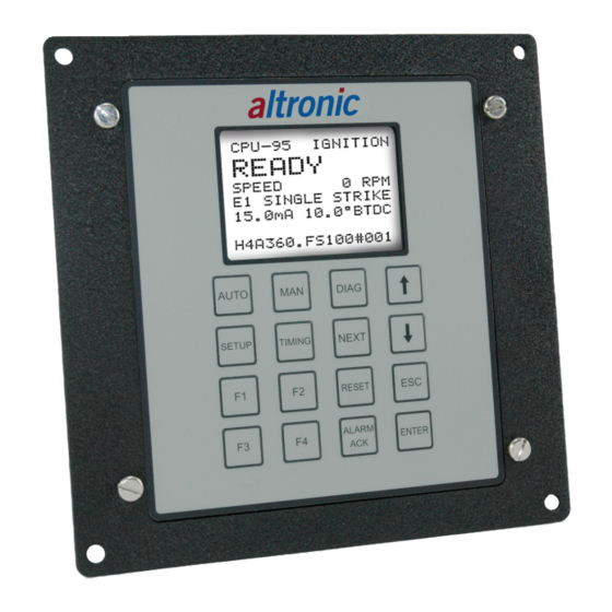
- Page 4 The bit stream selection (E1,E2,E3) and the single-strike/multi-strike type (SS or MS) are described in the middle of the upper line in small characters. CPU-95EVS OI 7-13 All rights reserved © ALTRONIC, LLC 2013...
- Page 5 Out switch (switch opens), by changing the state of the Fault Out switch (switch opens), and by displaying the Fault message. The various types of diagnostic faults are described in SECTION 10.0. CPU-95EVS OI 7-13 All rights reserved © ALTRONIC, LLC 2013...
- Page 6 4.9 From the HOME SCREEN, pressing the NEXT key allows you to cycle through the configuration comments which describe the configuration of the ignition system. PRESS TO NEXT GO TO NEXT The configuration screens are shown starting on the next page. CPU-95EVS OI 7-13 All rights reserved © ALTRONIC, LLC 2013...
- Page 7 AT 20mA 24° RETARD USER SPECIFIED DESCRIPTION NEXT RPM RETARD CURVE DESCRIPTION RETARD 10° BELOW 100rpm RAMP TO 0° AT 200rpm USER SPECIFIED DESCRIPTION NEXT LOCATION: USER SPECIFIED DESCRIPTION NEXT CPU-95EVS OI 7-13 All rights reserved © ALTRONIC, LLC 2013...
- Page 8 USER SPECIFIED COMMENTS NEXT SPECIAL USER COMMENTS AREA #2 USER SPECIFIED COMMENTS NEXT PRESS NEXT TO RETURN TO HOME SCREEN NEXT PRESS ESC. FROM ANY SCREEN TO RETURN TO HOME SCREEN CPU-95EVS OI 7-13 All rights reserved © ALTRONIC, LLC 2013...
- Page 9 REPRESENTS THE CYCLE TYPE OF THE ENGINE 2 = TWO-CYCLE 4 = FOUR-CYCLE REPRESENTS THE ALTRONIC PATTERN CODE (SEE FORM CPU-95EVS AL) REPRESENTS THE NUMBER OF GEAR TEETH OR HOLES TO BE SENSED REPRESENTS A DESIGNATOR FOR CPU-95EVS VERSION 1 REPRESENTS THE CURRENT LOOP RETARD CURVE TYPE A = 0°...
- Page 10 5.0 ADJUSTING GLOBAL RETARD 5.1 Global retard is an adjustment affecting the timing of all cylinders equally. This adjustment can be equated to the manual timing switch of the Altronic CPU-90 system. Adjustments made as described below will be in effect until another adjustment is made.
- Page 11 6.1 Several options exist with regard to global timing modes. Once the global timing mode menu is entered, as described below, the status of each option can be viewed and changed. FROM PRESS TIMING THEN AT PRESS THEN AT PRESS CPU-95EVS OI 7-13 All rights reserved © ALTRONIC, LLC 2013...
- Page 12 RPM. To configure the RPM retard curve, reference form CPU-95EVS PI. AT THE NOTE: DISPLAY NEXT SHOWS RPM OPTION MAP OFF. SCREEN TURN TURN NEXT EXIT NEXT OPTION CPU-95EVS OI 7-13 All rights reserved © ALTRONIC, LLC 2013...
- Page 13 1 STEP RET = ON. OPTION SCREEN NOTE: LOWER CASE 1 STEP RETARD = OFF. NOTE: 1 STEP RETARD NOT CONFIGURED. TO GO NEXT INCREASE DECREASE BACK TO EXIT FIRST CPU-95EVS OI 7-13 All rights reserved © ALTRONIC, LLC 2013...
- Page 14 7.3 The individual timing adjustment screen identifies the primary output to be adjusted, and the degrees of offset in use for the output. THEN AT NOTE: 2.5 degrees advance for output A. NEXT ADVANCE RETARD SELECT EXIT NEXT CYL. CPU-95EVS OI 7-13 All rights reserved © ALTRONIC, LLC 2013...
- Page 15 Reference SECTION 7.0 to adjust individual (temporary) offsets. AT THE FIRST OPTION SCREEN PRESS TO PRESS PRESS TO ENTER NEXT SAVE FOR NEXT EXIT OFFSETS OPTION CPU-95EVS OI 7-13 All rights reserved © ALTRONIC, LLC 2013...
- Page 16 8.3 The next mode function can be used to reset all cylinder offset values to zero (both temporary memory and EEPROM memory). AT THE NEXT OPTION SCREEN PRESS to press PRESS to NEXT ENTER RESET FOR NEXT exit OFFSETS OPTION CPU-95EVS OI 7-13 All rights reserved © ALTRONIC, LLC 2013...
- Page 17 Note 2: The use of Multi-Strike firings may tend to accelerate spark plug elec- trode erosion. Note 3: The Multi-Strike feature is used to select spark profiles 4-6. See figure 2. NEXT TURN TURN NEXT EXIT option MULTI MULTI CPU-95EVS OI 7-13 All rights reserved © ALTRONIC, LLC 2013...
- Page 18 9.4 The next setup screen is used to adjust the engine overspeed setpoint. The setpoint can be adjusted in increments of 10 rpm to a maximum of 2550 rpm. NEXT INCREASE DECREASE NEXT EXIT OPTION CPU-95EVS OI 7-13 All rights reserved © ALTRONIC, LLC 2013...
- Page 19 EEPROM settings under the Setup or Timing menus can be changed. This feature can be used to provide limited protection from random changes by inexperienced operators. TO TURN TO TURN NEXT ON PRO- OFF PRO- NEXT EXIT TECTION TECTION OPTION CPU-95EVS OI 7-13 All rights reserved © ALTRONIC, LLC 2013...
- Page 20 NEXT VERIFY EXIT ENTER tures prior to selecting the test mode PURGED operation. Pressing the enter key again is a confirmation of this action. CPU-95EVS OI 7-13 All rights reserved © ALTRONIC, LLC 2013...
- Page 21 ROTATION SEQUENCE 791963-8X: ALL, A, B, C, D, E, F, K, L 791963-16X: ALL, A, B, C, D, E, F, K, L, M, N, P, R, S, T, U, V, ALL CPU-95EVS OI 7-13 All rights reserved © ALTRONIC, LLC 2013...
- Page 22 USB driver on the CDROM. The USB port virtual com port baud rate can be set to the following: 9600, 19200, 38400, 57600, 115200. The DEBUG mode is used by the factory for testing purposes. CPU-95EVS OI 7-13 All rights reserved © ALTRONIC, LLC 2013...
- Page 23 EXIT ENTER THE MENU NEXT MENU PRESS TO MODIFY THE VALUE PRESS TO PRESS TO PRESS TO NEXT ADVANCE TO GO TO THE EXIT ENTER THE NEXT NEXT MENU SELECTION CPU-95EVS OI 7-13 All rights reserved © ALTRONIC, LLC 2013...
- Page 24 It is possible to setup the system so that any change to the ignition timing will trigger a datalog event (an exception report). Exception reports are automatically generated for alarms or shutdowns. CPU-95EVS OI 7-13 All rights reserved © ALTRONIC, LLC 2013...
- Page 25 EXIT ENTER THE MENU NEXT MENU PRESS TO MODIFY THE VALUE PRESS TO PRESS TO PRESS TO NEXT ADVANCE TO GO TO THE EXIT ENTER THE NEXT NEXT MENU SELECTION CPU-95EVS OI 7-13 All rights reserved © ALTRONIC, LLC 2013...
- Page 26 Alarm Out switch will return to its closed position. Alarm LED will flash to indicate that an alarm is present but acknowledged. CPU-95EVS OI 7-13 All rights reserved © ALTRONIC, LLC 2013...
- Page 27 When too many gear-tooth pulses are seen without a reset pulse. When there are no Hall-effect pickup pulses or when the pick- ups are not synchronized. CPU-95EVS OI 7-13 All rights reserved © ALTRONIC, LLC 2013...
- Page 28 This screen indicates that the firing pattern configuration data saved in EEPROM memory is incorrect or incomplete. The EEPROM memory must be reprogrammed or replaced. CPU-95EVS OI 7-13 All rights reserved © ALTRONIC, LLC 2013...
- Page 29 E coil (Cyl 5). No spark occurred since the demand was greater than the output capability of the coil. CPU-95EVS OI 7-13 All rights reserved © ALTRONIC, LLC 2013...
- Page 30 Clears all diagnostic faults from memory. • Clears a latched shutdown condition when the input is no longer grounded. • Causes temporary cylinder timing offsets to be overwritten from EEPROM memory. CPU-95EVS OI 7-13 All rights reserved © ALTRONIC, LLC 2013...
- Page 31 HOME SCREEN TO VIEW DISPLAY SCREEN PRESS TO VIEW PRESS TO VIEW GRAPH OF TO ADJUST NEXT CURRENT SPARK CYLINDER CYLINDER OFFSET PRESS PRESS NEXT TO VIEW NEXT EXIT CYLINDER CPU-95EVS OI 7-13 All rights reserved © ALTRONIC, LLC 2013...
- Page 32 No Secondary Spark CAVG > user programmable threshold (typ. 250) Low From Engine (EAVG - CAVG) > user programmable threshold (typ. 20) High From Engine (CAVG - EAVG) > user programmable threshold (typ. 20) CPU-95EVS OI 7-13 All rights reserved © ALTRONIC, LLC 2013...
- Page 33 (specifically, voltage demand) of the engine. There are known differences between various types of Altronic coils, and slight variations are normal between coils of the same type. In order to maximize the usefulness of the cylinder spark reference number, it is recommended that all coils be of the same type and vintage (production date).
- Page 34 To disable diagnostic, set value to zero. PRESS TO VIEW PRESS NEXT TO VIEW GRAPH OF TO ADJUST NEXT CURRENT SPARK CYLINDER CYLINDER OFFSET PRESS TO PRESS TO INCREASE DECREASE THRESHOLD THRESHOLD CPU-95EVS OI 7-13 All rights reserved © ALTRONIC, LLC 2013...
- Page 35 HI FROM ENGINE threshold, a diagnostic warning for that cylinder will occur. This test will identify a cylinder whose voltage demand is too far above the average engine voltage demand. Default = 60 CPU-95EVS OI 7-13 All rights reserved © ALTRONIC, LLC 2013...
- Page 36 CYLINDER CYLINDER SPARK OFFSET PRESS TO ADJUST THE PRESS TO EXIT TIMING CURRENT SELECTED CYLINDER TIMING OFFSET 13.3 The second graph shows each individual cylinder. The solid line is the CPU-95EVS OI 7-13 All rights reserved © ALTRONIC, LLC 2013...
- Page 37 Pressing ENTER the second time will display the ↕ and allows the user to change the zoom level using the arrow keys. Pressing ENTER a third time exits the adjustments. CPU-95EVS OI 7-13 All rights reserved © ALTRONIC, LLC 2013...
- Page 38 PRESS TO VIEW THE GRAPH IN SECTION 13.2 CURRENT SELECTED CYLINDER PRESS TO ADJUST THE PRESS TO ADJUST THE TIMING CURRENT SELECTED CURRENT SELECTED CYLINDER SPARK OFFSET CYLINDER TIMING OFFSET PRESS TO EXIT CPU-95EVS OI 7-13 All rights reserved © ALTRONIC, LLC 2013...
- Page 39 PROGRAM SELECTED OPTION OPTION If a previous ignition has been stored in the display module, an overwrite confirmation is displayed. PRESS TO PRESS TO CONTINUE ENTER EXIT WITH THE BACKUP CPU-95EVS OI 7-13 All rights reserved © ALTRONIC, LLC 2013...
- Page 40 The second phase is to read the ignition again for verification. PRESS TO ABORT After reading and verifying, the contents are written to the eeprom of the display module. Done. PRESS TO EXIT CPU-95EVS OI 7-13 All rights reserved © ALTRONIC, LLC 2013...
- Page 41 Next, the display module will read back what was written for verification. With verification complete, the ignition is reset. WARNING: THE CPU-95EVS MUST BE PROGRAMMED PRIOR TO USE. REFER TO PROGRAMMING INSTRUCTIONS CPU-95EVS PI 4-08. CPU-95EVS OI 7-13 All rights reserved © ALTRONIC, LLC 2013...
- Page 42 Done. PRESS TO EXIT CPU-95EVS OI 7-13 All rights reserved © ALTRONIC, LLC 2013...
- Page 43 10001 to 10064 can be made which will return all 64 values as a group of 8 bytes. These registers also support an Altronic custom function 101 which will return a descriptive label for each specific register. The custom label function can be used to reduce the need for the Modbus master to maintain a current listing of all of the register labels for each unit.
- Page 44 MISC REMOTE INPUT 10063 spare 10064 spare 10065 20 OUTPUT MODULE 10066 18 OUTPUT MODULE 10067 DUAL CAPACITOR MODULE 10068 WITH FILTER MODULE 10069 spare 10070 spare 10071 spare 10072 spare CPU-95EVS OI 7-13 All rights reserved © ALTRONIC, LLC 2013...
- Page 45 WARN OPEN PRIMARY (C or B1) Warning 10113 spare (D or B2) Warning 10114 WARN HI VOLTAGE (D or B2) Warning 10115 WARN NO SECONDARY SPK (D or B2) Warning CPU-95EVS OI 7-13 All rights reserved © ALTRONIC, LLC 2013...
- Page 46 (M or E1) Warning 10156 WARN LO FROM ENGINE (M or E1) Warning 10157 WARN HI FROM ENGINE (M or E1) Warning 10158 WARN LO VOLTAGE (M or E1) Warning CPU-95EVS OI 7-13 All rights reserved © ALTRONIC, LLC 2013...
- Page 47 10198 WARN LO VOLTAGE (T or K2) Warning 10199 WARN SHORTED PRIMARY (T or K2) Warning 10200 WARN OPEN PRIMARY (T or K2) Warning 10201 spare (U or L1) Warning CPU-95EVS OI 7-13 All rights reserved © ALTRONIC, LLC 2013...
- Page 48 10239 WARN SHORTED PRIMARY Warning 10240 WARN OPEN PRIMARY Warning 10241 spare Warning 10242 WARN HI VOLTAGE Warning 10243 WARN NO SECONDARY SPK Warning 10244 WARN LO FROM ENGINE Warning CPU-95EVS OI 7-13 All rights reserved © ALTRONIC, LLC 2013...
- Page 49 READ ONLY 30031 CYL TIMING OFFSET (D,D,B2) READ ONLY 30032 CYL TIMING OFFSET (E,E,C1) READ ONLY 30033 CYL TIMING OFFSET (F,F,C2) READ ONLY 30034 CYL TIMING OFFSET (K,G,D1) READ ONLY CPU-95EVS OI 7-13 All rights reserved © ALTRONIC, LLC 2013...
- Page 50 30073 DIAG OFFSET (F,F,C2) READ ONLY 30074 DIAG OFFSET (K,G,D1) READ ONLY 30075 DIAG OFFSET (L,H,D2) READ ONLY 30076 DIAG OFFSET (M,K,E1) READ ONLY 30077 DIAG OFFSET (N,L,E2) READ ONLY CPU-95EVS OI 7-13 All rights reserved © ALTRONIC, LLC 2013...
- Page 51 30136 REF. ANGLE OF RESET PIN degrees * 10 READ ONLY 30137 MAX INDIVIDUAL OFFSET degrees * 10 READ ONLY 30138 CYL TIM. OFF. (A,A,A1) degrees * 10 READ ONLY CPU-95EVS OI 7-13 All rights reserved © ALTRONIC, LLC 2013...
- Page 52 30252 InStat 177-192 READ ONLY 30253 InStat 193-208 READ ONLY 30254 InStat 209-224 READ ONLY 30255 InStat 225-240 READ ONLY 30256 InStat 241-256 READ ONLY 30257 – RESERVED 65535 30384 CPU-95EVS OI 7-13 All rights reserved © ALTRONIC, LLC 2013...
- Page 53 CYLINDER LABEL (U,S,L1) 65535 READ/WRITE 40231 CYLINDER LABEL (V,T,L2) 65535 READ/WRITE 40232 CYLINDER LABEL ( U,M1) 65535 READ/WRITE 40233 CYLINDER LABEL ( V,M2) 65535 READ/WRITE 40234 CYLINDER LABEL ( 65535 READ/WRITE CPU-95EVS OI 7-13 All rights reserved © ALTRONIC, LLC 2013...
- Page 54 40252 EAVG Bar Graph Spread 40253 RTC Year year 2007 2099 READ/WRITE 40254 RTC Date 65535 msb=month, lsb=day 40255 RTC Time 65535 msb=hour, lsb=minutes 40256 Key Commands 65535 READ/WRITE CPU-95EVS OI 7-13 All rights reserved © ALTRONIC, LLC 2013...
- Page 55 1. RS-485 SERIAL COMMUNICATIONS PORT 2. MISCELLANEOUS INPUT – ONE STEP RETARD (DEFAULT), ALSO MULTI-STRIKE, MAX. ENERGY LEVEL (CONFIGURED THROUGH P.C.) 3. 4–20mA CURRENT LOOP INPUT 4. AUXILIARY RS-485 MODBUS RTU PORT 5. USB CPU-95EVS OI 7-13 All rights reserved © ALTRONIC, LLC 2013...
- Page 56 FIGURE 2: CPU-95EVS DIRECTED ENERGY SPARK PROFILES E1 MS: Emulates MS mode of standard CPU-95. E1 SS: Emulates SS mode of standard CPU-95. E2 SS: A medium current single spark event. E2 MS: Tri-spark event with one high current and two medium current sparks.
Need help?
Do you have a question about the CPU-95 and is the answer not in the manual?
Questions and answers