Advertisement
Quick Links
www.altronicinc.com
INSTALLATION INSTRUCTIONS
WARNING:
DEVIATION FROM THESE INSTRUCTIONS MAY LEAD TO IMPROPER OP-
WARNING:
ERATION OF THE MACHINE WHICH COULD CAUSE PERSONAL INJURY
TO OPERATORS OR OTHER NEARBY PERSONNEL.
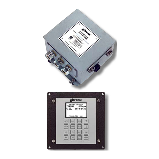
1.0 SYSTEM DESCRIPTION
1.1
The Altronic CPU-95, DC-powered ignition system is a microproces-
sor-based capacitor discharge system designed for application on
natural gas fueled engines. The system features crankshaft-trig-
gered timing accuracy and the capability to vary timing electroni-
cally by several means, including an external 4-20 mA control signal
connected to the optional Display Module. The system is field-pro-
grammable and offers a variety of advanced control methods, emis-
sions reduction, primary and spark diagnostics, self diagnostics,
serial communications and engine protection features. The system
consists of two main parts: an engine mounted Ignition Module and
an optional user interface Display Module.
1.2
Various models of the Ignition Module are available:
791950-8
8-outputs, standard
791950-16
16-outputs, standard
791950-18
18-outputs, standard
791952-18
18-outputs, dual capacitor
791958-16
16-outputs, Varispark™ extended duration
1.3
The optional Display Module has a graphical, back-lit LCD display
that shows the operating status, engine RPM, energy level, single or
double-striking mode, current loop input value and ignition timing.
Additional display screens show set-up and diagnostic information.
1.4
To allow for a simple and economical upgrade of existing Altronic
CPU-90 installations, the CPU-95 utilizes the same ignition box mount-
ing layout, existing Altronic coils, magnetic pickups, Hall-effect
pickup and trigger magnet, pickup cables, primary wiring harness
and junction box(es).
1.5
Power requirement is 24 Vdc, 5 ampere nominal for typical applica-
tions. For Ignition Module 791958-16, use a supply rated for 24 Vdc, 10
amperes.
SEE SECTION 9.2 FOR DETAILS.
WARNING:
DEVIATION FROM THESE INSTRUCTIONS MAY LEAD TO IMPROPER
ENGINE OPERATION WHICH COULD CAUSE PERSONAL INJURY TO
OPERATORS OR OTHER NEARBY PERSONNEL.
THE IGNITION SYSTEM MUST BE CONFIGURED PRIOR TO
USE ON AN ENGINE. REFER TO SECTION 9.7 TO VIEW THE
CURRENT CONFIGURATION. REFERENCE FORM CPU-95 PI
FOR INSTRUCTIONS DESCRIBING HOW TO CONFIGURE THE
IGNITION SYSTEM. VERIFY EEPROM PROGRAMMING PRIOR
TO STARTING ENGINE.
CPU-95
DIGITAL IGNITION SYSTEM
MODELS 791950-8/16/18, 791952-18, 791958-16
FORM CPU-95 II 4-08
www.altronicinc.com
1
Advertisement

Related Manuals for Altronic 791950-8


Summary of Contents for Altronic 791950-8
- Page 1 Additional display screens show set-up and diagnostic information. To allow for a simple and economical upgrade of existing Altronic CPU-90 installations, the CPU-95 utilizes the same ignition box mount- ing layout, existing Altronic coils, magnetic pickups, Hall-effect pickup and trigger magnet, pickup cables, primary wiring harness and junction box(es).
-
Page 2: System Components
NOTE: The enclosure width When replacing an existing Altronic CPU-90 system, the CPU-95 Igni- tion Module can be mounted in place of the CPU-90 unit; the mount- is 1 inch larger than the ing footprint is identical to facilitate the changeover. - Page 3 5.0 MOUNTING FLYWHEEL GEAR/DRILLING FLYWHEEL HOLES The Altronic CPU-95 system requires a source of angular position pulses from the engine crankshaft. This can be a flywheel ring gear, a separately provided gear mounted on the crankshaft or specially drilled holes in the flywheel.
- Page 4 CPU-95 DIGITAL IGNITION SYSTEM 8.0 MOUNTING THE CYCLE TRIGGER (4-CYCLE ENGINE ONLY) The trigger magnet (260604 or 720002) must be mounted on the en- gine camshaft or other accessory drive operating at camshaft speed. An M8 (8 mm) tapped hole, 0.5 inches (13 mm) deep is required — SEE FIGURE 17 FIGURE 14 for details.
- Page 5 INSTALLATION INSTRUCTIONS IMPORTANT: For proper operation of the CPU-95 system, voltage and current supplied must be sufficient during all selected modes FIGURE 5 of operation. provides these details regarding the DC pow- er hookup: 1. CURRENT DRAW PER SYSTEM: Formula varies depending on number of outputs used, en- gine cycle and RPM, and use of the multi-strike feature.
- Page 6 Ignition Module. Use 24 AWG, UL style 1015 wire or shielded cable for these connections; the 24 AWG wire is available from Altronic under part number 603102 (black) or 603103 (white). A. SHUTDOWN INPUT (terminal 1):...
- Page 7 4-20 mA loop current from various 2-wire or 3-wire sources. The loop input is electrically isolated from all other terminals. Use 24 AWG, UL style 1015 wire, Altronic part number 603102 (black) or 603103 (white), SEE FIGURE 11 or equivalent for these connections.
-
Page 8: Primary Wiring
FIGURE 1 Refer to if it is desired to shorten the conduit length of the harness. Insert the connector into the Altronic CPU-95 Ignition Module receptacle and tighten hand-tight; then carefully tighten an additional one-sixth turn with a wrench. FIGURE 8... - Page 9 This lead can also be used for oscilloscope analysis. PLEASE NOTE THE FOLLOWING APPLICATION LIMITATIONS WARNING: BETWEEN THE CPU-95 IGNITION SYSTEM AND THESE ALTRONIC INSTRUMENTS: NOTE: Tachometer and DO-3300...
-
Page 10: Secondary Wiring
RFI on the operation of other nearby electronic equipment. Another option is the use of sup- pression ignition cable (Altronic part no. 503185). It is also essential to keep spark plug leads as short as possible and in all cases not longer than 24 inches (600 mm). -
Page 11: Dimensional Drawings
FIG. 6 COIL WIRING DIAGRAM, UNSHIELDED IGNITION SYSTEM FIG. 7 COIL WIRING DIAGRAM, SHIELDED IGNITION SYSTEM FIG. 8 HOOKUP DIAGRAM, IGNITION MODULE 791950-8 / 791950-16 FIG. 9 HOOKUP DIAGRAM,IGNITION MODULE 791950-18 / 791952-18 FIG. 10 WIRING DIAGRAM, IGNITION MODULE FIG. 11 WIRING DIAGRAM, DISPLAY MODULE FIG. - Page 12 CPU-95 DIGITAL IGNITION SYSTEM FIG. 1 SHIELDED HARNESS CONDUIT LENGTH ADJUSTMENT FORM CPU-95 II 4-08...
- Page 13 INSTALLATION INSTRUCTIONS FIG. 2 PICKUP MOUNTING DETAIL www.altronicinc.com...
- Page 14 CPU-95 DIGITAL IGNITION SYSTEM FIG. 3 FLYWHEEL HOLE DRILLING FORM CPU-95 II 4-08...
- Page 15 INSTALLATION INSTRUCTIONS FIG. 4 IGNITION SYSTEM BASIC LAYOUT www.altronicinc.com...
- Page 16 CPU-95 DIGITAL IGNITION SYSTEM FIG. 5 DC POWER HOOKUP FORM CPU-95 II 4-08...
- Page 17 INSTALLATION INSTRUCTIONS FIG. 6 COIL WIRING DIAGRAM, UNSHIELDED IGNITION SYSTEM www.altronicinc.com...
- Page 18 CPU-95 DIGITAL IGNITION SYSTEM FIG. 7 COIL WIRING DIAGRAM, SHIELDED IGNITION SYSTEM FORM CPU-95 II 4-08...
- Page 19 INSTALLATION INSTRUCTIONS FIG. 8 HOOKUP DIAGRAM, IGNITION MODULE 791950-8 / 791950-16 www.altronicinc.com...
- Page 20 CPU-95 DIGITAL IGNITION SYSTEM FIG. 9 HOOKUP DIAGRAM,IGNITION MODULE 791950-18 / 791952-18 FORM CPU-95 II 4-08...
- Page 21 INSTALLATION INSTRUCTIONS FIG. 10 WIRING DIAGRAM, IGNITION MODULE www.altronicinc.com...
- Page 22 CPU-95 DIGITAL IGNITION SYSTEM FIG. 11 WIRING DIAGRAM, DISPLAY MODULE FORM CPU-95 II 4-08...
- Page 23 INSTALLATION INSTRUCTIONS FIG. 12 TIMING CURVE, 4-20 MA www.altronicinc.com...
- Page 24 CPU-95 DIGITAL IGNITION SYSTEM FIG. 13 MAGNET ASSEMBLY SALES DRAWING FORM CPU-95 II 4-08...
- Page 25 INSTALLATION INSTRUCTIONS FIG. 14 MAGNET ASSEMBLY SALES DRAWING www.altronicinc.com...
- Page 26 CPU-95 DIGITAL IGNITION SYSTEM FIG. 15 HALL-EFFECT PICKUP SALES DRAWING FORM CPU-95 II 4-08...
- Page 27 INSTALLATION INSTRUCTIONS FIG. 16 MAGNETIC PICKUP SALES DRAWING www.altronicinc.com...
- Page 28 CPU-95 DIGITAL IGNITION SYSTEM FIG. 17 IGNITION MODULE MOUNTING DIMENSIONS FORM CPU-95 II 4-08...
- Page 29 INSTALLATION INSTRUCTIONS FIG. 18 DISPLAY MODULE MOUNTING DIMENSIONS www.altronicinc.com...
- Page 30 CPU-95 DIGITAL IGNITION SYSTEM FIG. 19 NEMA 3R ENCLOSURE MOUNTING DIMENSIONS FORM CPU-95 II 4-08...
Need help?
Do you have a question about the 791950-8 and is the answer not in the manual?
Questions and answers