Table of Contents
Advertisement
Advertisement
Table of Contents

Related Manuals for Interlogix True Vision TVP-5104


Summary of Contents for Interlogix True Vision TVP-5104
- Page 1 TruVision IP PTZ Camera Installation Guide P/N 1073398-EN • REV A • ISS 15MAY18...
- Page 2 Copyright © 2018 United Technologies Corporation, Interlogix is part of UTC Climate, Controls & Security, a unit of United Technologies Corporation. All rights reserved. Trademarks and Trade names used in this document may be patents trademarks or registered trademarks of the manufacturers or vendors of the respective products.
- Page 3 FCC conditions This device complies with Part 15 of the FCC Rules. Operation is subject to the following two conditions: (1) This device may not cause harmful interference. (2) This Device must accept any interference received, including interference that may cause undesired operation.
- Page 4 2013/56/EU & 2006/66/EC (battery directive): This product contains a battery that cannot be disposed of as unsorted municipal waste in the European Union. See the product documentation for specific battery information. The battery is marked with this symbol, which may include lettering to indicate cadmium (Cd), lead (Pb), or mercury (Hg).
- Page 5 Contact information For contact information and to download the latest manuals, tools, and firmware, go to the manuals/tools/firmware web site of your region. Americas: www.interlogix.com EMEA: www.firesecurityproducts.com Manuals are available in several languages Australia/New Zealand: www.utcfs.com.au...
-
Page 7: Table Of Contents
How to access the SD card slot 11 Restore default settings 12 Mounting the PTZ camera 13 Using the camera with an Interlogix NVR or Hybrid DVR or another system 18 Using the camera with a TruVision Navigator 18 Accessing the camera over the internet 18... -
Page 8: Product Overview
H.264/H.265) Contact information and manuals/tools/firmware For contact information and to download the latest manuals, tools, and firmware, go to the web site of your region. Americas: www.interlogix.com EMEA: www.firesecurityproducts.com Manuals are available in several languages. Australia/New Zealand: www.utcfs.com.au Installation Guide... -
Page 9: Installation
Installation This section provides information on how to install the cameras. Installation environment When installing your product, consider these factors: • Electrical: Install electrical wiring carefully. It should be done by qualified service personnel. Always use a proper Hi-PoE (Max. 60 W) switch or a 24 VAC UL listed Class 2 or CE certified power supply to power the camera. -
Page 10: Package Contents
Cleaning: Do not touch the sensor modules with fingers. • If cleaning is necessary, use a clean cloth with some ethanol and wipe the camera gently. If the camera will not be used for an extended period of time, put on the lens cap to protect the sensors from dirt. - Page 11 Battery Disposal sheet Equipment Disposal • • sheet IR PTZ camera IR PTZ camera Hinged back box • • Installation Guide...
- Page 12 Hex wrench CD with Configuration • • manual and TruVision Device Manager Installation guide Equipment Disposal • • sheet Battery Disposal sheet • CAUTION: Use direct plug-in UL listed power supplies marked Class 2/CE certified or LPS (limited power source) of the required output rating as listed on the unit.
-
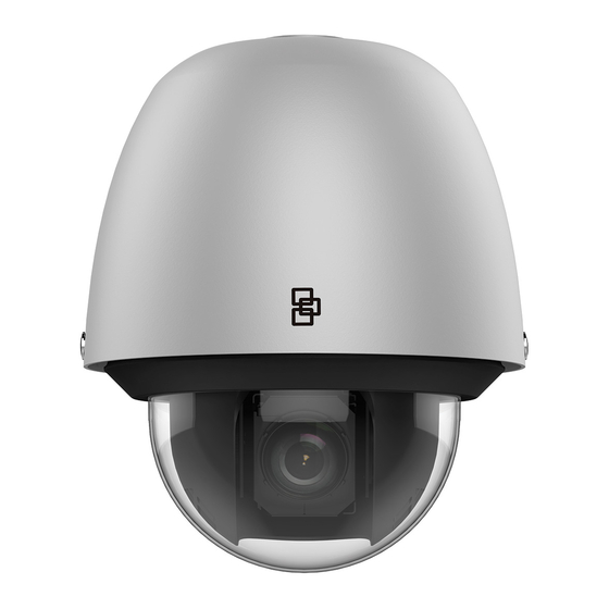
Page 13: Camera Description
CAUTION: Risk of explosion if the battery is replaced by an incorrect type. Dispose of used batteries according to the instructions. Camera description Figure 1: PTZ camera Installation Guide... - Page 14 ⑧ Ethernet RJ45 RS-485 port connector a. Orange RS-485+ Audio in b. Yellow RS-485- (RED/WHITE)/out port (BLUE/WHITE) 960H analog output 2 alarm outputs 24 VAC power supply (BROWN, Location to attach the ORANGE/WHITE) safety lanyard 7 alarm inputs Reset button (GREEN, BLUE, PURPLE, GRAY, WHITE,...
- Page 15 BLACK/WHITE, BROWN/WHITE) Note: Hi-PoE (Max. 60 W) or 24 VAC is required to power the PTZ. Figure 2: IR PTZ camera Ethernet RJ45 2 alarm outputs connector (WHITE_RED, WHITE_PURPLE) 960H analog output Audio in (PURPLE)/out 7 alarm inputs port (PINK) Installation Guide...
-
Page 16: Ir Illuminators
(YELLOW_BLUE, RS-485 port YELLOW_ORANGE, a. Orange RS-485+ YELLOW_GREEN, YELLOW_BROWN, b. Yellow RS-485- YELLOW_PURPLE, 24 VAC power supply YELLOW_GREY, YELLOW_RED) Note: Hi-PoE (Max. 60 W) or 24 VAC is required to power the PTZ. IR illuminators The IR PTZ camera’s built-in IR illumination provides high- quality video in low-light environments, even when there is no other illumination available. -
Page 17: How To Access The Sd Card Slot
relay must be used to prevent electric shock and damage to the device. See Figure 3 below. Figure 3: External alarm output How to access the SD card slot PTZ camera Open the black plastic access panel on the back of the PTZ block. -
Page 18: Restore Default Settings
IR PTZ camera Open the black plastic access panel on the back of the PTZ block. The SD card location is shown in the figure below. SD card slot Reset button Restore default settings To reset the camera to default settings, press and hold the Reset button for 10 s and power on or reboot the camera. -
Page 19: Mounting The Ptz Camera
Mounting the PTZ camera Mount the wall mount (not included) on the mounting surface) You can mount the camera on indoor/outdoor solid walls. The following requirements are mandatory preconditions for wall mounting: The wall must be thick enough to install the expansion ... - Page 20 Use the wall mount as a template to mark out the mounting area. Provide an access hole in the mounting surface for the interconnect cables. Drill four screw holes in the wall according to the mounting holes, and then insert M8 expansion anchors (included with the wall mount) into the mounting holes.
- Page 21 Reinstall the bubble assembly, making sure that the rubber gasket remains in place. Fully tighten the four hex head screws to ensure a good seal. Route the PTZ cable harness through the wall mount. A cable access panel is provide to ease the overall installation.
- Page 22 To mount the IR PTZ camera: Pull the interconnect cables through the wall mount prior to installing the mount. Install the upper base to the wall mount. Clip the IR IP PTZ on to the upper base. Connect the IR IP PTZ safety lanyard to the IR PTZ, as shown below.
- Page 23 Route the interconnect cables to the PTZ camera. Connect the corresponding network/power/RS-485 cables. Raise the IR IP PTZ into position and tighten the three hex bolts, using the supplied hex wrench, to secure the PTZ to the upper base. Installation Guide...
-
Page 24: Using The Camera With An Interlogix Nvr Or Hybrid Dvr Or Another System
Using the camera with a TruVision Navigator A camera must be connected to an Interlogix NVR or hybrid DVR to be operated by TruVision Navigator. Please refer to the TruVision Navigator user manual for instructions on operating the camera with the TruVision Navigator. -
Page 25: Specifications
and upper case letters, and special characters : _ - , . * & @ / $ ? Space. The password must contain characters from at least two of these groups. We also recommend that you reset your password regularly. For high security systems, it is particularly recommended to reset the password monthly or weekly for better protection. -
Page 26: Truvision Ir Ip Ptz Dome
TruVision IR IP PTZ dome Electrical Voltage input 24 VAC Power consumption Hi-PoE (Max. 60W) Miscellaneous Connectors 24 VAC, Alarm In/Out, RS-485, Ethernet RJ45 connector, Audio In/Out, 960H Output Operating temperature -40 to +65°C (-40 to 149°F) Dimensions 266.6 × 396.4 mm (10.50 ×... - Page 27 Figure 1: Straight-through cable White/Orange White/Orange Orange Orange White-Green White-Green Blue Blue White/Blue White/Blue Green Green White/Brown White/Brown Brown Brown Figure 2: Cross-over cable White/Orange White/Orange Orange Orange White-Green White-Green Blue Blue White/Blue White/Blue Green Green White/Brown White/Brown Brown Brown Please make sure your connected cables have the same pin assignment and color as above before deploying the cables in your network.
Need help?
Do you have a question about the True Vision TVP-5104 and is the answer not in the manual?
Questions and answers