Interlogix TruVision TVA-1101 Installation Manual
Covert ip camera
Hide thumbs
Also See for TruVision TVA-1101:
- Configuration manual (70 pages) ,
- Installation manual (24 pages)

Related Manuals for Interlogix TruVision TVA-1101


Summary of Contents for Interlogix TruVision TVA-1101
- Page 1 TruVision Covert IP Camera Installation Manual P/N 1072912-EN • REV B • ISS 22MAY15...
- Page 2 © 2015 United Technologies Corporation Copyright Interlogix is part of UTC Building & Industrial Systems, a unit of United Technologies Corporation. All rights reserved. Trade names used in this document may be trademarks or registered trademarks Trademarks and of the manufacturers or vendors of the respective products.
-
Page 3: Table Of Contents
Set up the camera 7 Complete the installation 13 Configuration 13 Access the SD card 13 Use the camera with an Interlogix NVR or Hybrid DVR or another system 14 Use the camera with TruVision Navigator 14 Specifications 14 TruVision Covert IP cameras 14... -
Page 4: Product Overview
Product overview This is the installation manual for the following TruVision Covert IP camera models: TVA-1101 (1.3MPX IP ATM/covert camera, WDR, PAL) TVA-3101 (1.3MPX IP ATM/covert camera, WDR, NTSC) TVL-0101 (TruVision Covert Lens, 1.3MPx, Pinhole, 3.7mm@ F2.3, 2m ... -
Page 5: Package Contents
• Servicing: Do not attempt to service this camera yourself. Any attempt to dismantle or remove the covers from this product will invalidate the warranty and may also result in serious injury. Refer all servicing to qualified service personnel. Cleaning: Do not touch the sensor modules with fingers. If cleaning is •... -
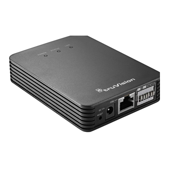
Page 6: Camera Description
Camera description Figure 1: Covert IP camera description Covert camera unit: Lens: (purchased separately) 1. Main unit 3. L-shape lens 2. Mounting rack 4. L-shape lens cover 9. Power indicator 5. L-shape lens mounting bracket 10. Status indicator 6. Pinhole lens 11. -
Page 7: Which Adhesive Tape To Use
LINK Flashing amber Network connection is functioning properly Unlit No network connection Which adhesive tape to use There are two types of adhesive tape (1 mm and 4 mm) included in the package that are used to attach the lens to the surface. 1 mm adhesive tape 4 mm adhesive tape When the surface is around 4 mm... - Page 8 Fix the mounting bracket on the rear panel of the main unit with four screws. Hook the top catch of the main unit on the rack. Gently press the lower part of the camera against the rack so that it snaps into position on the rack. Note: If there is already a standard rail installed, you can directly snap the main unit onto the installed rail.
- Page 9 To install the pinhole lens: Note: Before installing the device, ensure that the mounting surface is suitable for adhesive mounting. Drill a hole in the mounting surface. Note: Please ensure that the hole size is appropriate for the camera lens. Remove the protective film from the adhesive tape on the pinhole lens mounting bracket.
- Page 10 To install the L-shape lens Drill a hole in the mounting surface. Remove the protective film from the adhesive tape on the L-shaped mounting bracket. Align the bracket with the drilled hole and stick the bracket on the mounting surface. Note: Please ensure that the hole size is appropriate for the camera lens.
- Page 11 To install the Cylinder lens Fix the mounting base of the bracket to the ceiling with the supplied screws. Hood the bracket cover to the mounting base. Screw the bracket to the mounting base. Loop the fixed focal unit with the loop of the bracket, and tighten it with the supplied screw.
- Page 12 Align the assembled fixed focal unit to the bracket, and rotate the unit to tighten the unit with the bracket. Loosen the knob to adjust the surveillance angle, and then tighten the lock nut to complete the installation. Knob Lock nut Installation Manual...
-
Page 13: Complete The Installation
Complete the installation Connect the RJ-12 connector of the lens cable to the main unit. Connect an audio device. Connect a 3.5 mm microphone and an audio output device to the AUDIO IN and AUDIO OUT interfaces. Connect a Probridge or another device via the RS-232 port. Connect alarm input/output devices. -
Page 14: Use The Camera With An Interlogix Nvr Or Hybrid Dvr Or Another System
Use the camera with TruVision Navigator A camera must be connected to an Interlogix NVR or hybrid DVR in order to be operated by TruVision Navigator. Please refer to the TruVision Navigator user manual for instructions on operating the camera with the TruVision Navigator. -
Page 15: Pin Definitions
Pin definitions There are eight wires on a standard UTP/STP cable and each wire is color- coded. The following shows the pin allocation and color of straight and crossover cable connection: Figure 2: Straight-through cable White/Orange White/Orange Orange Orange White-Green White-Green Blue Blue...
Need help?
Do you have a question about the TruVision TVA-1101 and is the answer not in the manual?
Questions and answers