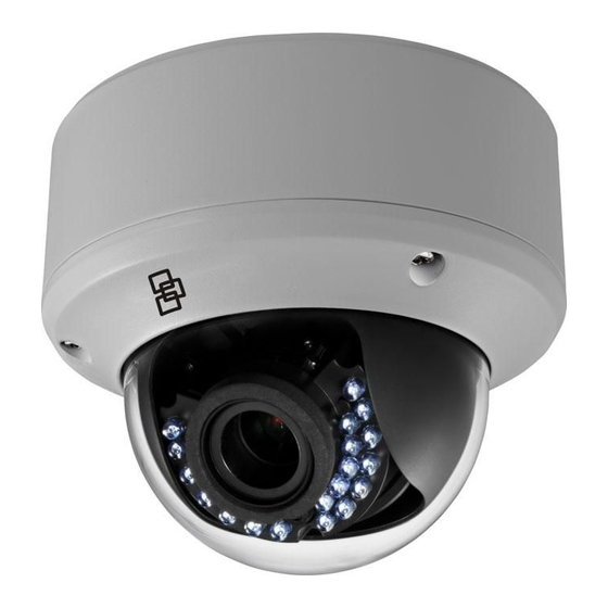
Interlogix TruVision TVD-2402 Installation Manual
High definition tvi vandal dome
Hide thumbs
Also See for TruVision TVD-2402:
- Configuration manual (10 pages) ,
- Installation manual (4 pages) ,
- Installation manual (20 pages)

Related Manuals for Interlogix TruVision TVD-2402


Summary of Contents for Interlogix TruVision TVD-2402
- Page 1 TruVision High Definition TVI Vandal Dome Installation Guide TVD-2402/TVD-4402 TVD-2404/TVD-4404 TVD-2405/TVD-4405 P/N 1073166-EN • REV B • ISS 26MAY17...
-
Page 3: Table Of Contents
Content Product overview 4 Camera description 6 Installation 9 Operating temperature range 14 Program 14 Setup menu 19 Specifications 21 Legal and Regulatory information 23 Installation Guide... -
Page 4: Product Overview
Product overview This is the Installation Guide for the TruVision High Definition TVI dome TVD-2402/TVD-4402,TVD- 2404/TVD-4404 and TVD-2405/TVD-4405. This guide describes a standard installation. Package contents Camera with power 4 screws and 4 and video output anchors for wall or cables ceiling installation Template... - Page 5 Hex wrench Monitor output cable Spare rubber Installation Guide knockout There is a rubber knockout on the camera back box. This is for future use. • WEEE and Battery Disposal sheets Installation Guide...
-
Page 6: Camera Description
Camera description TVD-2402/TVD4402: Dome liner TVI video output cable (grey) Bubble Back box Lens Switch (Left = Power cable WDR / Right = CVBS video output CVBS) cable (black) Menu button 10. CVBS output port Installation Guide... - Page 7 TVD-2404/4404 and TVD2405/4405: Dome liner TVI video output cable (grey) Bubble Back box Lens Switch (Left = Power cable WDR / Right = CVBS video output CVBS) cable (black) Menu button 10. CVBS output port Installation Guide...
- Page 8 Note: Please check the camera output settings before setting up a system. The TVI video output can be only connected to DVR with TVI signal input. The CVBS output supports a standard CVBS monitor (or test monitor), an encoder or a DVR. For 720P Dome cameras TVD-2402/TVD- 4202, the CVBS and TVI output can not be used at the same time.
-
Page 9: Installation
Installation To install the camera on a ceiling: Using the template, place it level against the mounting surface and mark the position of the mounting holes. Following all local safety regulations, drill and prepare the mounting holes. Remove the camera from its back box. Loosen the three screws on the edge of the bubble with the supplied hex wrench. - Page 10 Secure the back box to the ceiling with the supplied screws. Note: Please remove the rubber knockout for cable routing outside of the camera, when required. Installation Guide...
- Page 11 Using a 75-ohm coaxial video cable, connect the camera TVI video output to a TVI DVR, and connect a 12 VDC or 24 VAC power supply to the power cable. Align the camera with the back box and tighten the screws to fasten the camera to the back box.
- Page 12 Rotate the camera block to adjust the pan direction [0 to 355°]. Loosen the tilting lock screw. Rotate the camera block to adjust the tilt direction [0 to 90°]. Tighten the tilting lock screw. Rotate the camera lens holder [0 to 355°] to adjust the lens to the surveillance angle.
- Page 13 Loosen the zoom lever and move the screw between T (Tele) and W (Wide) to obtain the appropriate angle of view. Tighten the zoom lock screw. Loosen the focus lever and move the screw between F (Far) and N (Near) to obtain the optimum focus.
-
Page 14: Operating Temperature Range
Operating temperature range The operating temperature of the TVD-2402/4402 and TVD-2404/4404 cameras is -30 to +60 °C (-22 to +140 °F). When the camera initially starts up, the heater will start to work automatically when the temperature is below -10 °C (14 °F). However, with continuous operation the heater will not work until the internal temperature drops below -30°C (-22 °F). - Page 15 Using the camera buttons Menu Please press the button to call up the OSD menu and select an OSD item. Press the button up/down to move the cursor up or down to an OSD item. Press the button left/right to move cursor left or right to adjust the value of a selected OSD item.
- Page 16 Access the PTZ menu of the connected DVR, set the TruVision-Coax protocol and use the PTZ control panel to configure the camera. Click Iris+ to access to the camera OSD menu and select an OSD item. Click the directional buttons UP or DOWN to move the cursor up or down to an OSD item.
- Page 17 Press the button of the TVS-C200 for a few seconds until you see the OSD menu display on the monitor. The button is also used to select an OSD item. Use the directional buttons to move the cursor and change a value. For more details, refer to the TVS-C200 user manual.
- Page 18 The TVI signal is blocked until the camera configuration is complete and the switch is reset to TVI. TVD-2404/TVD-4404 and TVD-2405/TVD-4405 The camera has the CVBS and TVI dual video outputs. The built-in switch is for WDR/CVBS selection. Set the built-in switch to CVBS to view the setup menu on a standard monitor.
-
Page 19: Setup Menu
Setup menu TVD-2402/TVD-4402: Installation Guide... - Page 20 TVD-2404/TVD-4404, TVD-2405/TVD-4405: Installation Guide...
-
Page 21: Specifications
Specifications Power supply 24 VAC/12 VDC Current TVD-2402/ TVD-4402: 12 VDC: 300 mA max. 24 VAC: 210 mA max. TVD-2404/TVD-4404: 12 VDC: 375 mA max. 24 VAC: 270 mA max. TVD-2405/TVD-4405: 12 VDC: 1 A max. 24 VAC: 500 mA max. TVD-2402/ TVD-4402: Power consumption... - Page 22 Dimensions 145.3 x 124.2 mm Ø 5.72 x 4.89 in. ) (Ø Installation Guide...
-
Page 23: Legal And Regulatory Information
Legal and Regulatory information Copyright: © 2017 United Technologies Corporation, Interlogix is part of UTC Climate, Controls & Security, a unit of United Technologies Corporation. All rights reserved. Trademarks and patents: Trade names used in this document may be trademarks or registered trademarks of the manufacturers or vendors of the respective products. -
Page 24: Contact Information
For proper recycling, return this product to your local supplier upon the purchase of equivalent new equipment, or dispose of it at designated collection points. For more information see: www.recyclethis.info. Contact information: For contact information, see www.interlogix.com or www.utcfssecurityproducts.eu Installation Guide...
Need help?
Do you have a question about the TruVision TVD-2402 and is the answer not in the manual?
Questions and answers