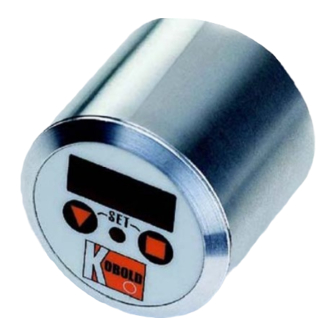
Summary of Contents for Kobold **C30R Series
- Page 1 Operating Instruction Supplement Compact Electronics Model:..C30R;..C30M ..C34P;..C34N...
-
Page 2: Table Of Contents
2. Note ......................3 3. Electrical Connection ..................3 4. Programming ....................5 5. Maintenance ....................12 6. Technical Information .................. 12 Manufactured and sold by: Kobold Messring GmbH Nordring 22-24 D-65719 Hofheim Tel.: +49(0)6192-2990 Fax: +49(0)6192-23398 E-Mail: info.de@kobold.com Internet: www.kobold.com Seite 2 ...C3... -
Page 3: Note
...C3... 2. Note This programming instruction is only a supplement to the operating instruction for the sensor. 3. Electrical Connection 3.1. General Attention! Make sure that the voltages in your plant correspond with the instrument voltages Make sure that the supply wires are de-energized. ... - Page 4 ...C3... 3.2. Compact Electronics: (..C30R, ..C30M) S witch out 2 + Vs S witch out 1 3.3. Compact Electronics: (..C34P, ..C34N) (0)4-20 mA + Vs S witch out 1 Terminals 3 and 5 are linked internally and can therefore be used either for the output signal or the power supply.
-
Page 5: Programming
...C3... 4. Programming Connect the compact electronics according to the previous wiring diagram and apply the specified voltage. The measuring range (upper range value) is displayed for 3 seconds after switch-on. 4.1. Key Function Standard mode (measuring mode) : pressing 3 sec. set-up mode : switchpoint/window point Set-up mode... - Page 6 ...C3... 4.3. Value Setting You can select Value setting in the main menu item (for example: Switching point, "SPo") by pressing the "" key. The structure shown below illustrates the universal routine for changing individual parameters. from the main menu item 1.
- Page 7 ...C3... 4.4. Set-up Mode 3 sec Code entering Value setting Swichting point 1 Value setting Switching point 2 Value setting Hysteresis Value setting Filter 7 Levels Value setting Contact 1 function Storing Frequency* Contact 2 function Storing Changing code Value setting *Only for sensors with impulse output ...C3...
- Page 8 ...C3... 3 sec Code entering Value setting Switching point Value setting Hysteresis Value setting Windowpoint Value setting Filter 7 levels Value setting Contact function Storing Frequency* Start current 7sec Value setting End current 7sec Value setting *Only for sensors with impulse output Seite 8 ...C3...
- Page 9 ...C3... 0-20 Analog output choosing 7sec Storing 4-20 Changing code Value setting 4.5. Main Menu Items Switching point The switching point is entered in menu item "SPo, SP1, SP2". A value in the range 000 to 999 may be chosen. A decimal point position is also assigned to this value.
- Page 10 ...C3... If the window point (duo point) is lower than or equal to the switching point, an error message is displayed (Er4), its value is then deleted and thus its function is disabled (applies to window point and switching point setting). Value setting is similar to switching point setting.
- Page 11 ...C3... Filter The filter function "Filt" generates the sliding average value from the measured values. The following values are available (see section 6.2 Settings): 1 / 2 / 4 / 8 / 16 / 32 / 64 The filter value determines the dynamic behaviour of the indicated value: high values result in a slow display response.
-
Page 12: Maintenance
...C3... 5. Maintenance Work on the electronics should only be carried out by the supplier, otherwise the guarantee is nullified. 6. Technical Information Display: 3-segment LED Display case: stainless steel Analogue output: (0)4 - 20 mA scalable (...C34 only) Transistor output: 1 (2) semiconductor PNP or NPN, set at the factory.


Need help?
Do you have a question about the **C30R Series and is the answer not in the manual?
Questions and answers