Table of Contents
Advertisement
Quick Links
Advertisement
Table of Contents

Related Manuals for Kobold MAN-SC


Summary of Contents for Kobold MAN-SC
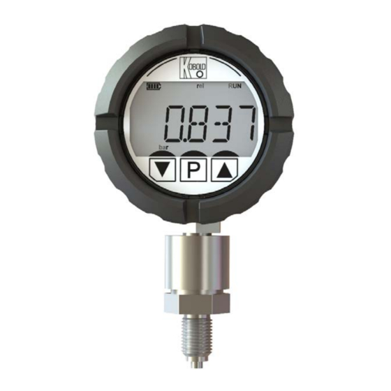
- Page 1 Operating Instructions Digital Pressure Gauge Model: MAN-SC/-LC MAN-LC MAN-SC...
-
Page 2: Table Of Contents
Orientation of the electronics housing ..........7 Electrical Connection ..................8 Inserting or changing the battery at MAN-SC ........8 Electrical connection with MAN-LC ............8 Layout of the LC display ................9 ... - Page 3 IO-Link system command table ............49 IO-Link ISDU parameter table ............49 Manufactured and sold by: Kobold Messring GmbH Nordring 22-24 D-65719 Hofheim Tel.: +49(0)6192-2990 Fax: +49(0)6192-23398 E-Mail: info.de@kobold.com Internet: www.kobold.com MAN-SC/-LC K07/0322 page 3...
-
Page 4: Note
In case of damage, please inform your parcel service / forwarding agent immediately, since they are responsible for damages during transit. Scope of delivery: The standard delivery includes: Digital Pressure Gauge model: MAN-SC/-LC MAN-SC only: 9 V block battery (IEC 6 LR 61) page 4 MAN-SC/-LC K07/0322... -
Page 5: Regulation Use
Therefore, any resulting damage is not the responsibility of the manufacturer. The user assumes all risk for such usage. 5. Operating Principle The devices of the type MAN-SC / -LC are used for measuring, monitoring and remote transmission of pressure-dependent operating processes in machines and systems. -
Page 6: Mechanical Connection
AF 24 G1/4 Flat seal-ring Ø5.5+0.2 according to DIN 16 258 Note: After each mechanical installation of the sensor, a zero point is required. (Menu item MISC / OFSET, not for instruments with absolute pressure sensor). page 6 MAN-SC/-LC K07/0322... -
Page 7: Orientation Of The Electronics Housing
Attention: a greater rotation than 180 ° in one direction leads to tearing the sensor connection lines and destroys the device. MAN-SC/-LC K07/0322 page 7... -
Page 8: Electrical Connection
7.1 Inserting or changing the battery at MAN-SC To insert or replace the battery, the rear cover of the MAN-SC must be turned 1/4 turn to the left in order to open the bayonet lock. The cover can then be removed from the rear and the battery compartment is accessible. -
Page 9: Layout Of The Lc Display
MAN-SC/-LC 8. Layout of the LC display MAN-SC/-LC K07/0322 page 9... -
Page 10: Button Function
The P key can be used to navigate in the settings menu: Short button press: Confirm selection or call up a submenu Long press: Leave the current menu level and switch to the higher-level menu level page 10 MAN-SC/-LC K07/0322... -
Page 11: Menu Operation
P key and the value adjuster is exited. For parameters with more than 5 adjustable locations, the display section is shifted to the right by selecting the adjustable location by a location to the right until the smallest adjustable location is displayed. MAN-SC/-LC K07/0322 page 11... -
Page 12: Menu Function - Menu Levels
If the P key is pressed for longer than 3 seconds, the device changes from measuring mode (RUN display symbol) to menu mode (PGM display symbol). Measuring mode Menu level Level 1 - 5 Parameter level (List selection or value entry) page 12 MAN-SC/-LC K07/0322... -
Page 13: Power Management (Man-Sc)
MAN-SC/-LC 11. Power management (MAN-SC) 11.1 Display of the battery status The battery life used is indicated by the number of segments in the battery symbol. Depending on the type of battery used and the ambient temperature, the display can be inaccurate or fluctuate by 1 segment. The battery status display is matched to the discharge characteristics of alkaline battery types. -
Page 14: Sleeping Mode
~ 13 µA Device restarts after waking up. Operational deepest sleep readiness after approx. 5 s. mode. No Suitable for storage of devices with inserted measuring battery function *: Average power consumption from a 9V battery page 14 MAN-SC/-LC K07/0322... -
Page 15: Display Orientation
MAN-SC/-LC 12. Display orientation The electronic unit of the MAN-SC / MAN-LC can be rotated by the user in 90 ° steps in order to adapt the display direction to the installation position: • Unscrew the display screw ring • Carefully remove the electronics unit from the electronics housing (note the limited cable length of the sensor and M12x1 connector!) •... - Page 16 MAN-SC/-LC MAN-LC page 16 MAN-SC/-LC K07/0322...
-
Page 17: Display Functions
5% of the measuring range span below the measuring range start value. Status Condition Overflow (↑) Measured value > MBE + (MBA - MBE)*0.05 Underflow (↓) Measured value < MBA - (MBA - MBE)*0.05 MAN-SC/-LC K07/0322 page 17... -
Page 18: Min / Max Memory Function
MAN-SC/-LC 13.4 MIN / MAX memory function The MAN-SC / -LC devices have a peak value storage function as standard. For both measured values pressure and force, the minimum and maximum measured value is continuously recorded and saved. The respective MIN or MAX values are displayed by pressing and holding the UP or DOWN key in the measuring mode. -
Page 19: Electrical Outputs (Only Man-Lc)
The device description files (IODD) are available in the IODDfinder, ioddfinder.io- link.com. Further information on IO-Link is available on the homepage www.io-link.com. MAN-SC/-LC K07/0322 page 19... -
Page 20: Device Parameterization
S VAL Start value for MONO and MBA … MBE 0,00 TRIAN [Unit] I VAL Interval increment (not for MBA … MBE 10,00 STATI mode) [Unit] INTER Number of intervals (not for 0 - 65000 STATI mode) page 20 MAN-SC/-LC K07/0322... - Page 21 2: F ALAR FUNC LIMIT Limit value function LIMIT / WINDO LIMIT WIND Window function TYPE Physical output type: NPN = NPN / PNP /PP negative switching, PNP = positive switching, PP = switching on both sides MAN-SC/-LC K07/0322 page 21...
- Page 22 2V value) 0-10V NAMUR Output overflow and underflow ENABL / DIAB ENABL behavior according to NAMUR Measured value for 0V output MBA - [10V] voltage (10V value must be [Unit] greater than 0V value) page 22 MAN-SC/-LC K07/0322...
- Page 23 FACT PASSW Factory settings menu, password protected (access only for service purposes) INFO General device information MAN-SC / MAN- Firmware version Vxx.xx Firmware revision ###### (Release date) * The ACT parameter must be set to ENABLED so that the other parameters are displayed...
-
Page 24: Parameter Table Man-Sc
MAN-SC/-LC 15.2 Parameter table MAN-SC Menu level Description Parameter value Parameter range default Level Level Level Level Level 5 value DISP REFRE Display refresh rate 1 - 10 s SLEEP Sleep mode 0,1,2 TOFF TimeOut time 0 - 120 min. -
Page 25: Process Of Device Parameterization
** The offset function is not available for devices with an absolute pressure sensor 15.3 Process of device parameterization The MAN-SC / -LC pressure sensor is pre-parameterized at the factory. In the event of subsequent changes to pressure or force measurement units, the parameters that depend on this are converted and adjusted accordingly. -
Page 26: Display (Main Menu Disp)
The "refresh rate" can be increased in steps from 1 s to 10 s. An increase in the refresh rate time causes an increased "filtering" of the display value. 15.4.2 Sleep mode (parameters SLEEP and TOFF, only MAN-SC) See section 11.2 15.4.3 Display layout (LAY submenu) Here you can select whether 1 measured value (SING) or 2 measured values (ALTE) are displayed alternately. -
Page 27: Measurement (Main Menu Meas)
15.6 Measurement (main menu MEAS) The measurement variables provided by the transducer are listed under the “MEAS” menu. With the pressure sensor MAN-SC / -LC these are: • Pressure measurement value (measurement variable 0, submenu "0: P" • Force measurement value (measurement variable 2, submenu "2: F"... -
Page 28: Outputs (Main Menu Out1, Out2, Only Man-Lc)
The different output types are optimized for different types of application. The following table contains the application recommendations for the various output types. If the outputs are not used according to the recommendations, measurement deviations may occur and the desired functionality will not be achieved. page 28 MAN-SC/-LC K07/0322... - Page 29 (with limit function) or if the measured value is outside the defined window (window function), a rectangle is displayed around the respective symbol Sp1 or Sp2 (see Fehler! Verweisquelle konnte nicht gefunden werden.). Status display alarm function MAN-SC/-LC K07/0322 page 29...
- Page 30 "switching threshold" and the "lower threshold". The monitored window decreases in each case by the amount of the "hysteresis". If the switching output is to be active within the window, the parameter "switching function" must be changed from N/O to N/C. page 30 MAN-SC/-LC K07/0322...
- Page 31 [SUPPR] before the switching output is activated. With this function, sporadic exceeding of limit values can be safely suppressed. The response time of the output is generally extended according to the value of the SUPPR parameter. MAN-SC/-LC K07/0322 page 31...
- Page 32 Note 1: If the "Value 20 mA" parameter is set smaller than the end of the measuring range, the accuracy of the output current value is reduced. Note 2: The load for the current output must not be greater than 500 Ω. page 32 MAN-SC/-LC K07/0322...
- Page 33 Note 1: If the value is set smaller than the end of the measuring range, the accuracy of the voltage value output is reduced. Output behavior 4-20 mA and 2-10 V Output behaviour 0-20 mA and 0-10 V MAN-SC/-LC K07/0322 page 33...
- Page 34 KofiCom is an in-house communication standard for service purposes. This function is only available for factory service. 15.7.5 IO-Link (parameter IOLIK, OUT1) If OUT1 is set to IOLIK, the IO-Link functionality can be used via this output. page 34 MAN-SC/-LC K07/0322...
-
Page 35: User Service (Main Menu User)
"PASSW". 15.8.4 Simulation timeout (SAS parameter) Specifies the time in minutes after which the simulation is automatically ended. 15.9 Factory service (main menu FACT) Access is only intended for authorized persons and is password-protected. MAN-SC/-LC K07/0322 page 35... -
Page 36: Info (Main Menu Info)
The firmware version of the device is displayed in this info option Firmware revision (parameter REV) The firmware revision of the device is displayed in this info option 16. Maintenance If the medium to be measured is not contaminated, the device is maintenance-free. page 36 MAN-SC/-LC K07/0322... -
Page 37: Technical Data
0(4)-20 mA max. load 500 Ω 0(2)-10 V , (R ≥ 50 kΩ, load error ≤ 1%) Load Control input (OUT1) MIN/MAX RESET OUT1, High active, 0 < U < 10 V 15 V < U < Vs High MAN-SC/-LC K07/0322 page 37... -
Page 38: Device Delivery Status
MAN-SC/-LC IO-Link (OUT1): Manufacturer ID: 1105 (decimal), 0x0451 (hex) Name of manufacturer: Kobold Messring GmbH IO-Link Specification: V1.1 Bitrate: COM2 Minimal cycle time: 10 ms SIO-Mode: yes (OUT1 in configuration IO-Link) Block parameterisation: yes Operational readiness: 10 s Max. cable length: Housing: Ø... -
Page 39: Order Codes
Diaphragm seal model and application data to be specified in clear text. Application Index on the last two pages of the data sheet to be filled out, or discuss with your local KOBOLD technical sales office. For a summary of diaphragm seal models and possible ranges, see page 11 and following. - Page 40 M2x16 and 8-pin M12 connector (only for MAN- LC…) Switching capacity per contact: 30 VAC/DC, max. 1 A ZUB-MANS-KAP01 Rubber protection sleeve MAN-SC/-LC, black ZUB-MANS-KAP01 Rubber protection sleeve MAN-SC/-LC, orange *: The separate operating instructions must be observed when installing and commissioning the relay retrofit...
- Page 41 MAN-SC/-LC MAN-SC/-LC K07/0322 page 41...
-
Page 42: Dimensions
MAN-SC/-LC 20. Dimensions MAN-SC MAN-LC page 42 MAN-SC/-LC K07/0322... - Page 43 MAN-SC/-LC Rubber protection sleeve ZUB-MANS-KAP01 (optional) MAN-SC/-LC K07/0322 page 43...
-
Page 44: Disposal
(Cd, Hg, Li or Pb) of the heavy metal that is decisive for the classification as containing pollutants: 1. „Cd" stands for cadmium 2. „Hg" stands for mercury 3. „Pb" stands for lead 4. „Li" stands for lithium Electrical and electronic equipment page 44 MAN-SC/-LC K07/0322... -
Page 45: Io-Link Manufacturer's Declaration
MAN-SC/-LC 22. IO-Link manufacturer's declaration MANUFACTURER'S DECLARATION OF CONFORMITY Kobold Messring GmbH Nordring 22-24 65719 Hofheim Germany declare under our own responsibility that the product(s): MAN-LC****** (IO-Link Device) to which this declaration refers conform to: IO-Link Interface and System Specification, V1.1,... -
Page 46: Eu Declaration Of Conformity
MAN-SC/-LC 23. EU Declaration of Conformity We, KOBOLD Messring GmbH, Hofheim-Ts, Germany, declare under our sole responsibility that the product: Digital Pressure Gauge Model: MAN-SC/-LC to which this declaration relates is in conformity with the standards noted below: EN IEC 63000:2018 Technical documentation for the assessment of electrical... -
Page 47: Declaration Of Conformity
MAN-SC/-LC 24. UK Declaration of Conformity We, KOBOLD Messring GmbH, Hofheim-Ts, Germany, declare under our sole responsibility that the product: Digital Pressure Gauge Model: MAN-SC/-LC to which this declaration relates is in conformity with the standards noted below: BS EN IEC 63000:2018 Technical documentation for the assessment of electrical and electronic products with respect to the restriction of hazardous substances. -
Page 48: Appendix Io-Link Specification Man-Lc
Diagnostic information is sent to the IO-Link master by event in IO-Link mode and, in contrast to the status display in standard device mode, does not remain persistent. page 48 MAN-SC/-LC K07/0322... -
Page 49: Io-Link System Command Table
Device Status Information 0x0024 DeviceStatus device status (0) - Device OK UIntegerT (1) - Maintenance required (2) - Out of specification (3) - Functional check (4) - Failure 0x0025 DetaildDevice detaild device status max. ArrayT of Status OctetStrin MAN-SC/-LC K07/0322 page 49... - Page 50 Value from source 100,0 OUT1- FloatT alueMaxHz used for max. Hz Frequency scaling point Value0Hz 0x0160 OUT1CtrlFunction Controlinputfunction (0) - Off UIntegerT (1) - Memory Reset OUTPUT 2 0x0171 OUT2Source Source for the (0) - Pressure UIntegerT page 50 MAN-SC/-LC K07/0322...
- Page 51 2V Analog- scaling point Value10V 0x019A OUT2AnalogValue The value from the 100,0 OUT2Anal FloatT slot used for the 10V ogValue0V scaling point 0x01B OUT2Frequencyat The max. frequency in 1000 UIntegerT Hz for the output MAN-SC/-LC K07/0322 page 51...
- Page 52 0x0513 ValueInSiUnit Pressure value 999999,0 -999999,0 FloatT in SI unit [bar] 0x0517 MinValueInSiUnit Pressure min value in 999999,0 -999999,0 FloatT SI unit [bar] 0x051B MaxValueInSiUnit Pressure max value in 999999,0 -999999,0 FloatT SI unit [bar] page 52 MAN-SC/-LC K07/0322...
- Page 53 SI unit [N] 0x05DF MinValueInSiUnit Force min value 999999,0 -999999,0 FloatT in SI unit [N] 0x05E3 MaxValueInSiUnit Force max value 999999,0 -999999,0 FloatT in SI unit [N] Legend MRE Measuring Range End MRS Measuring Range Start MAN-SC/-LC K07/0322 page 53...
Need help?
Do you have a question about the MAN-SC and is the answer not in the manual?
Questions and answers