Table of Contents
Advertisement
Quick Links
Advertisement
Table of Contents

Subscribe to Our Youtube Channel
Related Manuals for Kobold MIK


Summary of Contents for Kobold MIK
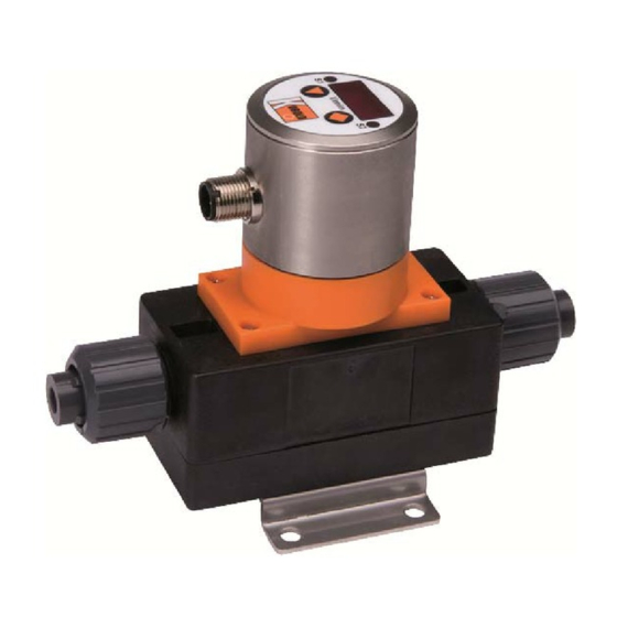
- Page 1 Operating Instructions Compact Magnetic-Inductive Flow Meter Model: MIK...
-
Page 2: Table Of Contents
MIK-...C34.................... 9 MIK-...Ex4R, MIK-...Gx4R ..............10 Operation ....................11 Switch point setting MIK-...S300, MIK-…S30D ........11 Counter electronics MIK-…Ex4R ............11 Dosing electronics MIK-…Gx4R ............11 Adjustments – Compact Electronics MIK-...C3........... 12 ... -
Page 3: Note
MIK Operating Instructions 4. Regulation Use Any use of the Compact Magnetic-Inductive Flow Meter, model: MIK, which exceeds the manufacturer’s specifications, may invalidate its warranty. Therefore, any resulting damage is not the responsibility of the manufacturer. The user assumes all risk for such usage. -
Page 4: Operating Principle
It is necessary for the correct function of the device that the current canal is always filled completely with medium. As of a minimum electrical conductivity of 30 µS/cm the MIK works within the guaranteed margins of error. The conductivity of the medium is continuously monitored by the device’s electronic system. -
Page 5: Deposits
5.4 Measuring electrodes The electrodes used with the MIK have a galvanic pick-off. They are in direct contact with the fluid and are fitted opposite one another, and insulated from the measuring tube. The standard electrodes are made of 1.4404 stainless steel or Hastelloy C4. -
Page 6: Mechanical Connection
max. operating pressure max. operating temperature In general the MIK is subjected to the same loads as the piping into which it is installed. The MIK should therefore be kept away from extreme loads, such as pressure surges with strong, dynamic pipe movements, vibrations in the proximity of centrifugal pumps, high temperature media, flooding etc. - Page 7 Gas bubbles Particle Free outlet MIK K10/0817 page 7...
-
Page 8: Electrical Connection
We recommend the use of wires with cross sectional area of min. 0,25 mm². Attention! The measuring electrodes are galvanically connected with the reference potential of the supply voltage and the signal output. 7.2 MIK-...S300 Output Output Common Output 7.3 MIK-...S30D... -
Page 9: Mik
7.4 MIK-...F300; MIK-...L3x3 Connection example MIK-...L3x3 n.c. n.c. Signal Signal 7.5 MIK-...L443 Signal 7.6 MIK-...C30.. 7.7 MIK-...C34.. 0(4)-20 mA Switch Out 2 Switch out 1 Switch Out 1 MIK K10/0817 page 9... -
Page 10: Mik
7.8 MIK-...Ex4R, MIK-...Gx4R Cable connection MIK-...E14R MIK-...G14R Wire number Counter electronics Dosing electronics +24 V +24 V 4-20 mA 4-20 mA n. c. Control 1* Reset part quantity Control 2* Relay S1 Relay S1 Relay S1 Relay S1 Relay S2... -
Page 11: Operation
8. Operation The units are preset and after electrical connection ready for operation. 8.1 Switch point setting MIK-...S300, MIK-…S30D Switch setting Switch point Switch function deactivated 10 % of f.s. 20 % of f.s. 30 % of f.s. 40 % of f.s. -
Page 12: Adjustments - Compact Electronics Mik
9. Adjustments – Compact Electronics MIK-...C3.. Connect the compact electronics according to previous connection diagram and supply with the indicated power supply. After power on, the measuring range (end current) will be shown for 3 seconds. 9.1 Button function In the standard mode (measuring mode) : Press 3 sec. -
Page 13: Value Setting
The flow chart below illustrates the universal routine for changing individual parameters. [From the main menu item] 1. Adjust position 2. Adjust position 3. Adjust position Adjust decimal point Save selected value save enter new value. [To the next main menu item] MIK K10/0817 page 13... -
Page 14: Set-Up Mode
9.4 Set-up mode Compact electronics MIK-...C30.. 3 sec Code entering Value setting Swichting point 1 Value setting Switching point 2 Value setting Hysteresis Value setting Filter 7 Levels Value setting Contact 1 function Storing Frequency Contact 2 function Storing Changing code... - Page 15 Compact electronics MIK-...C34.. 3 sec Code entering Value setting Switching point Value setting Hysteresis Value setting Windowpoint Value setting Filter 7 levels Value setting Contact function Storing Frequency Start current 7sec Value setting End current 7sec Value setting MIK K10/0817...
-
Page 16: Main Menu Items
(switching point minus hysteresis; window point plus hysteresis). Example: Switch point 100 L/min; Hysteresis: -2.5 L/min The electronics switches when 100 L/min is exceeded and switches back when the reading under-runs below 97.5 L/min. page 16 MIK K10/0817... - Page 17 The integrated step function detector reacts to a change of value corresponding to approx. 6.25% of the full scale value. As soon as a step function signal is detected, the instantaneous measured value is directly indicated in the display. MIK K10/0817 page 17...
- Page 18 Start current selection (0-20 mA or 4-20 mA). The indicated value at which 0(4) mA flow is entered in menu item start current. The indicated value at which 20 mA flow is entered in menu item end current. page 18 MIK K10/0817...
-
Page 19: Maintenance
If it is necessary to clean the sensor, the sensor can be rinsed with a suitable liquid. Fibre parts or large particles can be carefully removed with a cleaning cloth or similar. Work on the electronics can only be performed by the factory, or the warranty is otherwise voided. MIK K10/0817 page 19... -
Page 20: Technical Information
20 mm approx. 5,3 m/s 5,0...100 L/min approx. 3,3 m/s 8...160 L/min G 2 male 32 mm approx. 6,6 m/s 16...320 L/min approx. 3,6 m/s 25...500 L/min G 2¾ male 54 mm approx. 5,1 m/s 35...700 L/min page 20 MIK K10/0817... - Page 21 ± 20 % Power consumption: 80 mA Electrical connection: plug M12x1 Measuring range overflow: approx. 20,5 mA up to 103 % of f.s. MIK-...L443 (usage with AUF-3000) Output: 4-20 mA, 3-wire Max. load: 500 Ω Power supply: 24 V ± 20 %...
- Page 22 MIK-...C3xx (Compact electronics) Display: 3-digit LED Analogue output: (0)4...20 mA adjustable (only MIK-…C34x), Max. load: 500 Ω Switching output: 1(2) semiconductor PNP or NPN, set at factory, max. 300 mA Contact function: N/C, N/O, frequency, programmable (frequency output not calibrated, frequency at f.s.
-
Page 23: Order Codes
12. Order Codes Order details (Example: MIK-5NA 10 A F300 ) Model Range Connection set Electronics ..08..= 10…500 mL/min, frequency output G ½ ..F300 =M12-plug, 500 Hz ..A..= without ..F390 =M12-plug, ..10..= 0.05…1.0 50...1000 Hz L/min, ..P..= PVC-hose G ½... -
Page 24: Dimensions
13. Dimensions Model MIK-xxx08A/10A/15A G ½ MIK-xxx20A/25A G ¾ MIK-xxx30A/35A 49,5 29,5 MIK-xxx50A/55A G 1½ 65,6 31,5 MIK-xxx60A/65A MIK-xxx80A/85A G 2¾ MIK-...F3x0; MIK-...S30x; MIK-...L3x3 MIK-...L443 page 24 MIK K10/0817... - Page 25 MIK-...C3xx MIK-...Ex4R, MIK-...Gx4R MIK K10/0817 page 25...
- Page 26 G 3/4 G 1 1/2 not available not available G 2 3/4 not available Dimensions Connection set st. st. weld-on-ends Ø D1 Ø D2 G 1/2 10,2 G 3/4 13,5 G 1 1/2 G 2 3/4 60,3 page 26 MIK K10/0817...
-
Page 27: Eu Declaration Of Conformance
14. EU Declaration of Conformance We, KOBOLD Messring GmbH, Hofheim-Ts, Germany, declare under our sole responsibility that the product: Compact Magnetic-Inductive Flow Meter Model: MIK-… to which this declaration relates is in conformity with the standards noted below: EN 61320-1: 2013 Electrical equipment for control and instrumentation technology and laboratory use –...
Need help?
Do you have a question about the MIK and is the answer not in the manual?
Questions and answers