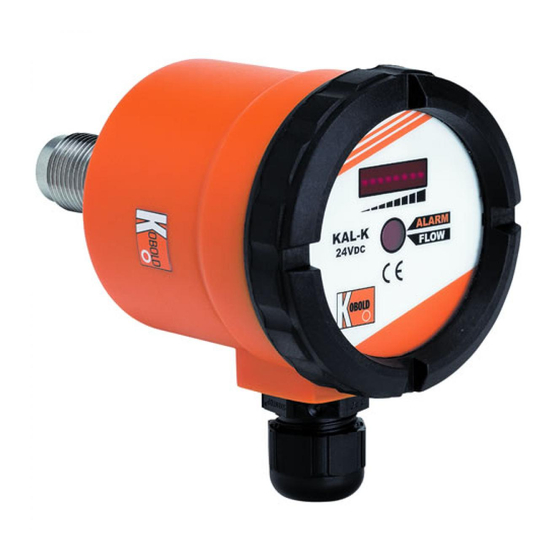
Kobold KAL-K User Instructions
Kal-4000 series.
thermal flow switch
Hide thumbs
Also See for KAL-K:
- Operating instruction (15 pages) ,
- Operating instructions manual (18 pages)
Summary of Contents for Kobold KAL-K
-
Page 1: User Instructions
KOBOLD KAL-K (KAL-4000 Series) Thermal Flow Switch User Instructions KOBOLD Instruments Inc. 1801 Parkway View Drive Pittsburgh PA 15205 Phone (412) 788-2830 • Fax (412)-788-4890 KAL-K_manual_8-29-06... -
Page 3: Table Of Contents
Table of Contents General..................... Specifications................... Mechanical Installation..............Electrical Connections..............Operation..................Calibration................Flow Setpoint Adjustment............Setting the KAL-K Output Transistor Type......KAL-K Diagnostics and Troubleshooting......Applications................Maintenance..................Arrival of Damaged Equipment............Need Help With Your KAL-K............List of Diagrams Diagram 2.1 Dimensions.............. -
Page 5: General
General The KOBOLD KAL-K (a.k.a. KAL-4000 Series) flow switch is intended for use in monitoring and control applications involving moderate flowrates of non-viscous or dirty liquids. The KAL-K flow switch uses the proven thermal dispersion principle and operates as follows: 1. - Page 6 Note: The flow ranges specified in the table above have been calculated for each pipe diameter based on the known velocity range of the KAL-K. It must be noted that flow in pipes is non-uniform across the pipe cross section, and approaches zero at the pipe wall. This...
-
Page 7: Diagram 2.1 Dimensions
KAL-K Diagram 2.1 Dimensions KAL-4215, 4315, 4320 KAL-4340S FM Rev. 8/29/06... -
Page 8: Mechanical Installation
KAL-K Mechanical Installation To install the KAL-K flow switch into your piping system, proceed as follows: 3.0.1 The KAL-K flow switch can be mounted in virtually any orientation as long as the piping is completely filled with fluid. It is recom- mended that the unit be installed in the upper hemisphere of the pipe when being used in horizontal piping runs. -
Page 9: Electrical Connections
KAL-K Electrical Connections Diagram 4.1 shows the layout of electrical connections, as well as other controls for the 24 VDC KAL-K. Diagram 4.2 shows the layout for 110 VAC versions. Diagram 4.1 Interior Controls Layout for 24VDC Versions Output Selector... -
Page 10: Kal-K Wiring 24 Vdc Versions
24 VDC, 300 mA power supply regulated to within ±10%. If the same power supply will be used to provide current to devices being switched by the KAL-K (e.g. relays), sufficient additional current must be available to power these devices. Diagram 4.4 shows the wiring for the 110 VAC versions of the KAL-K (suffix P03R). -
Page 11: Operation
Calibration 5.1.1 Zero Flow Calibration Calibration of the KAL-K electronics at zero system flow is necessary in order to obtain optimal performance from your KAL-K. This procedure is used to store data pertaining to the thermal characteristics of the fluid being monitored. -
Page 12: Flow Setpoint Adjustment
(approximately 10 seconds) all, or nearly all eight of the trend indicator LED’s should be lit. Flow Setpoint adjustment To adjust the flow setpoint on the KAL-K, refer to Diagram 4.1 for 24 VDC versions, and Diagram 4.2 for 110 VAC versions. Proceed as follows: 5.2.0.1 Adjust system flow to the value at which the setpoint is desired. -
Page 13: Setting The Kal-K Output Transistor Type
Setting the KAL-K Output Transistor Type (24 VDC versions Only) The KAL-K is shipped from the factory as a normally open (N/O) logic, PNP transistor output. The transistor output of the KAL-K can be field switched from PNP to NPN if desired by using SW 2. See Diagram 4.1. -
Page 14: Applications
KAL-K to activate a relay if: 1.It is necessary to switch an AC load (transistor switches only switch DC loads). 2.The DC load to be switched exceeds the current rating of the KAL-K transistor switch. -
Page 15: Maintenance
KAL-K Maintenance The KAL-K thermal flow switch is an electronically controlled device with no moving parts. As a result the unit is virtually maintenance free. Occasional cleaning of the immersed probe may be required if the fluid media is such that it tends to deposit or build up a film layer on the probe. - Page 17 KAL-K CAUTION PLEASE READ THE FOLLOWING WARNINGS BEFORE ATTEMPTING INSTALLATION OF YOUR NEW DEVICE. FAILURE TO HEED THE INFORMATION HEREIN MAY RESULT IN EQUIPMENT FAILURE AND POSSIBLE SUBSEQUENT PERSONAL INJURY. FM Rev. 8/29/06...
- Page 19 • Wiring and Electrical: Depending on the model, a supply voltage of 24 VDC ±10% or 110 VAC is used to power the KAL-K. The sensor systems should never exceed this rating. Electrical wiring of the sensor should be performed in accordance with all applicable national, state, and local codes.


Need help?
Do you have a question about the KAL-K and is the answer not in the manual?
Questions and answers