Table of Contents
Advertisement
Quick Links
Advertisement
Table of Contents

Summary of Contents for Kobold DPE Series
- Page 1 Operating Instructions Turbine-Wheel Flow Meter Model: DPE-...
-
Page 2: Table Of Contents
EU Declaration of Conformance ........14 UK Declaration of Conformity ........... 15 Manufactured and sold by: Kobold Messring GmbH Nordring 22-24 D-65719 Hofheim/Germany Tel.: +49(0)6192-2990 Fax: +49(0)6192-23398 E-mail: info.de@kobold.com Internet: www.kobold.com Page 2 DPE K12/1023... -
Page 3: Note
Please read these operating instructions before unpacking and putting the unit into operation. Follow the instructions precisely as described herein. The instruction manuals on our website www.kobold.com are always for currently manufactured version of our products. Due to technical changes, the instruction manuals available online may not always correspond to the product version you have purchased. -
Page 4: Regulation Use
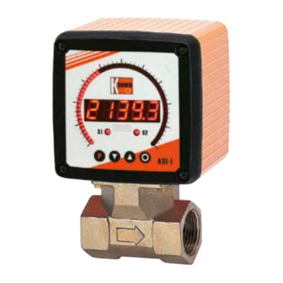
5. Operating Principles The Kobold flow meter model DPE is used for measuring and monitoring liquids. The device works according the well-known blade wheel principle. The six vane blade wheel is retained axially in a high-quality sapphire bearing. The sensor is supplied ready-to-install with pipe fittings or with weld-on sleeves. -
Page 5: Inlet And Outlet Path Straight Piping Requirements
6.2. Inlet and outlet path straight piping requirements Control valve 50 x D 5 x D 2 x 90°- elbow 3 - dimensional 40 x D 5 x D 2 x 90°- elbow 25 x D 5 x D DPE K12/1022 Page 5... - Page 6 90°- elbow or T - piece 20 x D 5 x D Reduction 15 x D 5 x D Extention 18 x D 5 x D Page 6 DPE K12/1023...
-
Page 7: Installation
Standard installation Ensure that the flow is in the direction of the arrow (universal positioning). Avoid pressure and tension loads on the device. Mechanically secure the inlet and outlet lines at a distance of 50 mm from the connections. -
Page 8: Electrical Connection
7. Electrical Connection 7.1. General information Attention! Make sure that the voltage values of your system correspond with the voltage values of the measuring unit. Make sure that the supply wires are de-energized. Connect and plug in the system according to the connecting plans. ... -
Page 9: Electronic Analyzer: Analog Output
7.3. Electronic analyzer: Analog output (..L303, ..L342, ..L343, ..L442) 3-wire (..L303, ..L343) n.c. Signal 2-wire (..L342) n.c. n.c. 2-wire, DIN plug connector (..L442) n.c. DPE K12/1022 Page 9... -
Page 10: Cable Outlet With M12X1 Angle Plug Electronic Options F3X And L3X
7.4. Cable outlet with M12x1 angle plug electronic options F3x and L3x When using a pre-assembled M12x1 connection cable with angled plug, the cable outlet is always aligned opposite to the flow direction. 7.5. Compact electronics: (..C30R, ..C30M, ..C34P, ..C34N) Operating instructions supplement for compact electronics with frequency output 7.6. -
Page 11: Commissioning - Electronic Analyzer
8. Commissioning - Electronic Analyzer 8.1. General These measuring devices are preset at the factory and ready for operation after the electric connection is completed. 8.2. Settings - Compact electronics Operating instructions supplement for compact electronics with frequency output 8.3. Settings - ADI electronic analyzer Operating instructions supplement for ADI electronic analyzer 9. -
Page 12: Technical Information
10. Technical Information Operating instructions, data sheet, approvals and further information via the QR code on the device or via www.kobold.com 11. Order Codes Operating instructions, data sheet, approvals and further information via the QR code on the device or via www.kobold.com 12. -
Page 13: Disposal
13. Disposal Note! Avoid environmental damage caused by media-contaminated parts Dispose of the device and packaging in an environmentally friendly manner Comply with applicable national and international disposal regulations and environmental regulations. Batteries Batteries containing pollutants are marked with a sign consisting of a crossed-out garbage can and the chemical symbol (Cd, Hg, Li or Pb) of the heavy metal that is decisive for the classification as containing pollutants: 1. -
Page 14: Eu Declaration Of Conformance
14. EU Declaration of Conformance We, KOBOLD Messring GmbH, Nordring 22-24, 65719 Hofheim, Germany, declare under our sole responsibility that the product: Turbine-Wheel Flow Meter Model: DPE -... to which this declaration relates is in conformity with the following EU directives... -
Page 15: Declaration Of Conformity
15. UK Declaration of Conformity We, KOBOLD Messring GmbH, Nordring 22-24, 65719 Hofheim, Germany, declare under our sole responsibility that the product: Turbine-Wheel Flow Meter Model: DPE -... to which this declaration relates is in conformity with the following UK directives stated below: S.I.


Need help?
Do you have a question about the DPE Series and is the answer not in the manual?
Questions and answers