
Related Manuals for Advantech AMAX-175 Series


Summary of Contents for Advantech AMAX-175 Series
- Page 1 User Manual AMAX-175x Series Open Frame Type 32-ch AMONet RS-485 Isolated Digital I/O Slave Modules...
- Page 2 No part of this manual may be reproduced, copied, translated or transmitted in any form or by any means without the prior written permission of Advantech Co., Ltd. Information provided in this manual is intended to be accurate and reliable. How- ever, Advantech Co., Ltd.
- Page 3 This product has passed the CE test for environmental specifications when shielded cables are used for external wiring. We recommend the use of shielded cables. This kind of cable is available from Advantech. Please contact your local supplier for ordering information.
- Page 4 AMAX-175x Series User Manual...
-
Page 5: Table Of Contents
Contents Chapter Introduction..........1 Features ....................2 Specifications .................... 2 1.2.1 General ..................2 1.2.2 Isolated Digital Input ..............3 1.2.3 Isolated Digital Output..............3 1.2.4 Environment.................. 3 Distributed Motion Product Selection Guide ..........4 Chapter Hardware Functionality .......5 Figure 2.1 AMAX-1752 Top View ..........6 Figure 2.2 AMAX-1754 Top View .......... - Page 6 AMAX-175x Series User Manual...
-
Page 7: Chapter 1 Introduction
Chapter Introduction This chapter gives an overview of the product features, and specifi- cations for AMAX-175x Series. Sections include: Features Specifications Distributed Motion Product Selection Guide... -
Page 8: Features
Products in the AMAX-175x Series are used to increase the number of digital input/ output channels for an AMONet RS-485 distributed motion control network. These extension slave modules connect serially by a simple and affordable Cat.5 LAN cable, reducing the wiring between driver and controller. This is very suitable for highly integrated machine automation applications. -
Page 9: Isolated Digital Input
1.2.2 Isolated Digital Input AMAX-1752: 32 DI Channels AMAX-1756: 16 DI Input type Dry contact Input voltage △ V *= 0~3V(Low Level) / 10~30V(High Level) (30V Max.) Input resistance 3.2K Input current 2mA Min. Input delay 100us Max. (Isolation delay) Input Isolation 2500Vdc *NOTE: △V=| IDICOMx - IDIx |. -
Page 10: Distributed Motion Product Selection Guide
Distributed Motion Product Selection Guide AMAX-175x Series User Manual... -
Page 11: Chapter 2 Hardware Functionality
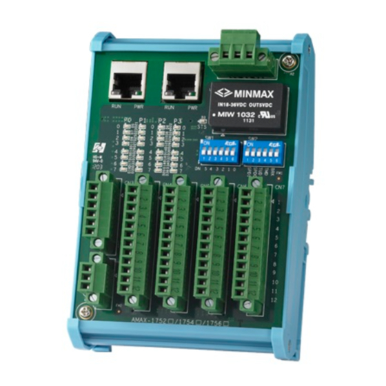
Chapter Hardware Functionality This chapter shows the hardware functionality of AMAX-175x Series. Sections include: Module Dimensions Power Connector BoardID Switch Configuration Setting LED Definition Pin Definition Signal Connection... - Page 12 AMAX-175x series is open frame type AMONET I/O modules which has on-board connectors for direct wiring and LED indicators to show the status. Here is the prod- uct dimension information: Figure 2.1 AMAX-1752 Top View AMAX-175x Series User Manual...
- Page 13 Figure 2.2 AMAX-1754 Top View AMAX-175x Series User Manual...
- Page 14 Figure 2.3 AMAX-1756 Top View Figure 2.4 AMAX-175x Middle View Note! The height does not include the male connector. The height of the male connector is 9mm. AMAX-175x Series User Manual...
-
Page 15: Module Power Connector(Cn1)
Module Power Connector(CN1) Descrption ± +VS input 24 V - VS Field Ground External Power Input Connector(CN2) Descrption +VEX (10-30 V -VEX Field Ground External Power Output Connector(CN3) Descrption +VEX (10-30 V - VEX AMAX-175x Series User Manual... -
Page 16: Board Id Switch (Sw1)
Board ID Switch (SW1) Label Note: Node Number=32xDN5+16xDN4+8xDN3+4xDN2+2xDN1+DN0. Default Setting: All the switches are in OFF status. Configuration Setting (SW2) Switch Label Description SPD1 Baud-Rate Setting SPD0 Time-Out Status Latch Specify watchdog timer time *For internal use only, please keep in OFF 2.5.1 Baud-Rate Setting SPD1... -
Page 17: Tmd
2.5.3 When the interval between data packets sent from a master card (ex. PCI-1202U) is longer than the specified interval, the watchdog timer times out. 20 Mbps 10 Mbps 5 Mbps 2.5 Mbps 20 ms 40 ms 80 ms 160 ms 5 ms 10 ms 20 ms... -
Page 18: Amax-1756
2.7.1 AMAX-1752 Description P0 (0~7) CN4 IDI 0~7 P1 (0~7) CN5 IDI 0~7 P2 (0~7) CN6 IDI 0~7 P3 (0~7) CN7 IDI 0~7 2.7.2 AMAX-1754 Description P0 (0~7) CN4 IDO 0~7 P1 (0~7) CN5 IDO 0~7 P2 (0~7) CN6 IDO 0~7 P3 (0~7) CN7 IDO 0~7 2.7.3... -
Page 19: Amax-1752
Pin Definitions 2.8.1 AMAX-1752 (32 DI) CN4 (P0) CN5 (P1) CN6 (P2) CN7 (P3) Pin1 COM 0 Pin1 COM 1 Pin1 COM 2 Pin1 COM 3 Pin2 IDI 0 Pin2 IDI 0 Pin2 IDI 0 Pin2 IDI 0 Pin3 IDI 1 Pin3 IDI 1 Pin3... -
Page 20: Amax-1756 (16 Di 16Do)
2.8.3 AMAX-1756 (16 DI 16DO) CN4 (P0) CN5 (P1) CN6 (P2) CN7 (P3) Pin1 COM 0 Pin1 COM 1 Pin1 +VEX Pin1 +VEX Pin2 IDO 0 Pin2 IDO 0 Pin2 IDO 0 Pin2 IDO 0 Pin3 IDO 1 Pin3 IDO 1 Pin3 IDO 1 Pin3... -
Page 21: Signal Connection
Signal Connection 2.9.1 Isolated Digital Output 2.9.2 Isolated Digital Input AMAX-175x Series User Manual... - Page 22 No part of this publication may be reproduced in any form or by any means, electronic, photocopying, recording or otherwise, without prior written permis- sion of the publisher. All brand and product names are trademarks or registered trademarks of their respective companies. © Advantech Co., Ltd. 2013...
Need help?
Do you have a question about the AMAX-175 Series and is the answer not in the manual?
Questions and answers