Table of Contents
Advertisement
Quick Links
Advertisement
Table of Contents

Related Manuals for 3D Systems SLS 380


Summary of Contents for 3D Systems SLS 380
- Page 1 SLS 380 User Guide Release Date: 6/12/2022 Original Instructions...
-
Page 2: Table Of Contents
1.5.2 SLS 380 Printable Maintenance Chart ..........................29 1.5.3 SLS 380 Preparing a Print Job Using 3D Sprint ......................31 1.5.5 SLS 380 Remove the Print Cake from the Process Chamber ..................33 1.5.6 SLS 380 Regular Maintenance ............................38 1.5.7 SLS 380 Shut Down the Printer ............................55 1.6 SLS 380 Service and Support ..............................56... -
Page 3: Sls 380 User Guide
3D Systems may (but shall not be obligated to) make improvements to this document from time to time. However, the Licensed User acknowledges that at any time after the expiration of the date of issuance, 3D Systems may institute a periodic charge or fee payable by the Licensed User in return for ongoing receipt of improvements. -
Page 4: Sls 380 Safety
READ THROUGH THE ENTIRE MANUAL FIRST. There are two levels of users of the SLS 380, based on the amount and type of training the user has received. The two levels of users (operators and certified service personnel), are described below. - Page 5 WARNING: IF ANY OF THE FOLLOWING SAFETY FEATURES FAILS, YOUR ACTIONS MAY BE ALL THAT WILL PREVENT POTENTIALLY HAZARDOUS OPERATING CONDITIONS. WARNING: IF THE SLS 380 IS USED IN A MANNER NOT SPECIFIED BY 3D SYSTEMS IN THIS MANUAL, THE PROTECTION PROVIDED BY THE EQUIPMENT MAY BE IMPAIRED.
- Page 6 Safety Symbols and Definitions The following are safety symbols that are common to 3D Systems guides. Some or all of these symbols may appear in this guide and/or in other SLS 380 documentation. CAUTION: Indicates the possibility of loss of data or damage to equipment.
-
Page 7: Sls 300 Safety Interlocks
Blackbody cleaning access cover IPM Cover Rear Filter Box 1.2.2 SLS 380 Laser Safety Laser Safety The SLS system contains a 100-watt, 10,600 nm, continuous-wave CO2 laser. This laser is rated for >100W average power over its operating lifetime, and can produce up to 150W average power when brand new. Under normal operating conditions, the average output power will not exceed 100W. -
Page 8: Sls 380 Nitrogen And Oxygen Safety
*From Safety Bulletin SB-2 - 1983-"1983 by the Compressed Gas Association, Inc. 1235 Jefferson Davis Highway, Arlington, VA 22202 1.2.4 SLS 380 Environmental Safety The following are environmental issues concerning the SLS 380: The SLS system emits no toxic substances when using materials approved by 3D Systems. 3D Systems, Inc. p/n 76-D084, Rev. B... -
Page 9: Sls 380 Electrical Safety
After any change to the electrical wiring, make sure the equipment is properly grounded. 1.2.6 SLS 380 Compressed Air Safety The SLS 380 uses compressed CDA (clean, dry air), supplied by the customer, for several functions in the printer and MQC. See facility guide for complete specifications. -
Page 10: Sls 380 Emergency Shutdown
WARNING: IN THE EVENT OF AN EMERGENCY, IMMEDIATELY HIT THE E-STOP BUTTON, LOCATED BELOW THE GUI SCREEN. 1.2.8 SLS 380 First Aid and Protective Equipment WARNING: IN THE CASE OF AN ACCIDENT WHILE USING ANY SLS EQUIPMENT, SEEK MEDICAL ATTENTION IMMEDIATELY. -
Page 11: Sls 380 Machine Disposal
Click here to view the label installation diagram! The SLS 380 has many warning labels throughout. This section details what those warning labels are and the locations of each type of label. It is important to use the machine with extreme caution to avoid situations that may be hazardous. The numbers in the Item column below correspond to the numbers in the images that follow. - Page 12 Possible electrical hazard on or behind panel with sticker Combustible Powder Warning - Machine uses combustible dust. Earth ground - shows the location of the earth ground wire - located in various places inside printer 3D Systems, Inc. p/n 76-D084, Rev. B...
- Page 13 Avoid eye or skin exposure to direct or scattered radiation. Max. power output: 150W, Wavelength: 10,600nm. EN/IEC 60825-1:2014 Hand Crush/Roller Pinch Point Take care to avoid possible pinch points in the process chamber. 3D Systems, Inc. p/n 76-D084, Rev. B...
- Page 14 Printer back Printer front Printer right, doors open Printer back, upper doors open 3D Systems, Inc. p/n 76-D084, Rev. B...
-
Page 15: Sls 380 Overview
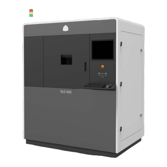
1.3 SLS 380 Overview The SLS 380, the new cutting-edge SLS production 3D printer from 3D Systems, takes SLS toughness, part quality, and manufacturing economics to the next level. Designed for smooth integration with your manufacturing workflow, the SLS 380 produces parts for a variety of end-use and functional prototyping applications in aerospace, medical, industrial design, and more. -
Page 16: Auxiliary Sls Equipment
Left Service Panel - Opened to access the sock filter during some maintenance procedures 1.3.2 Auxiliary SLS Equipment There are several auxiliary components which can accompany the SLS 380 system. 3D Systems, Inc. p/n 76-D084, Rev. B... -
Page 17: Sls 380 Components
MQC 600 Single and 600 Flex The MQC (Material Quality Control) 600 Systems are designed to be used as a material handling unit for many 3D Systems SLS printers, including the SLS 380. They are responsible for delivering material to the printer, storing and mixing fresh and used material, and breaking out the SLS parts from the print cake that is produced by the printer. - Page 18 USB Port - There is one standard auxiliary USB port connected to the control PC. 1.3.3.2 SLS 380 Electrical Cabinet The electrical cabinet is located on the back of the machine on the bottom. 3D Systems, Inc. p/n 76-D084, Rev. B...
- Page 19 The print cake Extraction Cylinder, Part Transfer Tray, and Part Transfer Cart are used to remove the print cake from the SLS 380 process chamber and transport it to an MQC 600 System. The system ships with the cylinder and tray. The transfer cart is optional.
-
Page 20: Sls 380 System Requirements And Setup
1.4.1 SLS 380 Power on Printer Your 3D Systems certified installer should have powered on your system for you. However, if the system or any of its components have unexpectedly shut down, or if you have shut them down, this section describes how to start up the system's components. -
Page 21: Sls 380 Installing-Setting Up 3D Sprint Software
Note: 3D Sprint software is always subject to updates. An announcement, along with release notes, will accompany a new software-version release. Note: On the SLS 380 PC, automatic updates in 3D Sprint are disabled. 3D Sprint should only be updated on the printer PC after verifying the update is supported on the system. -
Page 22: Sls 380 3D Sprint Additional Documentation
The MQC 600 Single or Flex System must be in Full-cycle mode for material to be sent from the blended bin to the SLS 380. Before selecting Full or Local cycle mode, the user should verify that the desired blend ratio is selected. (See the Material Guide for recommended ratio.) - Page 23 Options on the Viewer Menu While the system is in Build mode, you can set the following options for the Build Viewer. These options appear on the Viewer menu in the main window: 3D Systems, Inc. p/n 76-D084, Rev. B...
- Page 24 To display it, click the Change Parameter button; if the build is paused, click the Change Profiles/Prime Cycle button in the Pause Build dialog box. The buttons shown at the right will be referenced in the following sections. Modifying Part and Build Profiles Click the 3D Systems, Inc. p/n 76-D084, Rev. B...
- Page 25 At the end of a build, the Sinter application displays a summary of the actual build times, such as in the example below: Wait for Temperature Time - Total time the printer spent waiting to reach temperatures that were preset by the user. 3D Systems, Inc. p/n 76-D084, Rev. B...
- Page 26 Save to File - Click to save the build time report as a .txt file for future reference. Print - Click to send the build time report to a printer on your network. Launch LogManager - Click to open a more-detailed summary of the build. 3D Systems, Inc. p/n 76-D084, Rev. B...
- Page 27 The roller must be homed and stopped at left limit. • The piston must be homed and if empty, moved to the Start position. • The Roller Control and Piston Control dialog boxes must not be open. 3D Systems, Inc. p/n 76-D084, Rev. B...
- Page 28 Add Powder Layer dialog box to enable the button. The following parameters are available to set in the Add Powder Layer dialog: Note: You cannot close the Add Powder Layer dialog box while the printer is adding layers. 3D Systems, Inc. p/n 76-D084, Rev. B...
- Page 29 Sweeper Traverse 76 and 305 mm per Specifies the speed at Velocity second (3 and 12 which you want the inches per second) roller to travel. 3D Systems, Inc. p/n 76-D084, Rev. B...
- Page 30 1. At the end of calibration, IR Cal will report whether or not the sensor had to be calibrated and by how much it was out of spec in °C. Click OK to end IR Cal. 3D Systems, Inc. p/n 76-D084, Rev. B...
-
Page 31: Sls 380 Printable Maintenance Chart
Note: If the IR sensor core temperature is below 77°C/170 °F, the offline IR Calibration will wait until 77°C/170 °F has been reached, and then an additional 5 minutes for the core to stabilize. 1.5.2 SLS 380 Printable Maintenance Chart CAUTION: Before performing any printer-maintenance procedures, power the Printer down according to the... - Page 32 ) - Last performed: Exit Sinter application/Kill application ( link ) - Last performed: If chiller water level yields an alarm on the machine, add distilled water to the chiller tank. ( link 3D Systems, Inc. p/n 76-D084, Rev. B...
-
Page 33: Sls 380 Preparing A Print Job Using 3D Sprint
1.5.3 SLS 380 Preparing a Print Job Using 3D Sprint 3D Sprint is 3D Systems' exclusive software for importing CAD data and preparing it for printing. 3D Sprint can be used either on the SLS 380, remotely connected from your workstation, or off-line at a stand-alone workstation (Virtual Printer). - Page 34 1.5.3.3 Prepare 3D Sprint Build Packet The 3D Sprint Help menu offers full documentation for preparing build files and modifying build parameters for SLS 380 print jobs. To access the documentation: 1. In 3D Sprint, click the ? icon in the upper-right-hand corner of the screen.
-
Page 35: Sls 380 Remove The Print Cake From The Process Chamber
Note: The BPF for your job will be located in a folder (with its name ending in the job name) under the C:\dtm\build\jobs folder. 1.5.5 SLS 380 Remove the Print Cake from the Process Chamber Unload the Print Cake After a Print After a print and before part breakout, you must remove the print cake from the process chamber and transport it to the MQC System. - Page 36 1. Raise heaters. 1. Remove the Laser Window Baffle by turning it counterclockwise ¼-turn and pulling down. Put it in a safe, clean location and clean the lens before reinstalling it in the process chamber. 3D Systems, Inc. p/n 76-D084, Rev. B...
- Page 37 (see below). Failure to do so could damage the cylinder or the printer when closing the chamber doors. 1. Close and latch the inner process chamber door, and close the outer process chamber door. 3D Systems, Inc. p/n 76-D084, Rev. B...
- Page 38 If the print cake is light enough, simply carry it to the MQC 600 System. Removing the part cake is complete. Otherwise: b. Use the optional Part Transfer Cart. Continue to Step 12. 3D Systems, Inc. p/n 76-D084, Rev. B...
- Page 39 1. Take the following steps on the MQC UI screen: a. Setup/Service/Diag > b. Setup c. Cool->Time enabled d. Cool temp(C): 70 (if setting cool down temperature), or: e. Cool time (min): 300 3D Systems, Inc. p/n 76-D084, Rev. B...
-
Page 40: Sls 380 Regular Maintenance
3. To break out your parts, see the Break Out Parts section of the MQC 600 Single/Flex User Guide. 1.5.6 SLS 380 Regular Maintenance 1.5.6.1 Clean the Laser Window Frequency Daily The laser beam passes through the laser window into the process chamber. It is very important that all impurities are kept off the laser window. - Page 41 2. Place the laser window plug. 3D Systems, Inc. p/n 76-D084, Rev. B...
- Page 42 3. Bring the laser window baffle to a clean area and set it down on a clean cloth as shown. When not in use or being cleaned, cover it with lens tissue and secure the tissue over the lens using the tissue box. 3D Systems, Inc. p/n 76-D084, Rev. B...
- Page 43 Loosen the screws in a cross pattern so that the tension is relieved evenly. Remove the lid and set it to the side. Ensure to save the four screws. 3D Systems, Inc. p/n 76-D084, Rev. B...
- Page 44 5. Cover the lens with a lens tissue, and turn the assembly over so that the lens comes out. Carefully set the lens aside on your work table. 3D Systems, Inc. p/n 76-D084, Rev. B...
- Page 45 Use your finger to spread it across the surfaces. 9. Rinse the lens with warm water. If necessary, repeat washing and rinsing until the lens is thoroughly clean. 3D Systems, Inc. p/n 76-D084, Rev. B...
- Page 46 11. Return the lens to your work table and set it down on a clean lens cloth. Set a tissue on top of the lens and use a spray bottle like the one shown to spray a moderate amount of ethanol on the lens surface. 3D Systems, Inc. p/n 76-D084, Rev. B...
- Page 47 Ensure that the O-Ring is visible and that the lens is fully seated and flush with the housing. 3D Systems, Inc. p/n 76-D084, Rev. B...
- Page 48 Allen wrench to prevent over-tightening. Tighten in a cross pattern to even out the tension. 20. If not immediately reinstalling the laser window baffle, cover it as described in Step 2. 3D Systems, Inc. p/n 76-D084, Rev. B...
- Page 49 A clean blackbody will have a dark matte finish. It is important to inspect and clean before each build. Powder deposit on a blackbody surface can permanently change the surface if the powder sinters on the surface of the blackbody. 3D Systems, Inc. p/n 76-D084, Rev. B...
- Page 50 1. Remove the right-side panel to expose the black body. Remove the three screws from the black body cover. 1. Remove the metal black body bracket. 3D Systems, Inc. p/n 76-D084, Rev. B...
- Page 51 1. Remove the white black body cover. → 1. Place a small amount of ethanol on an SLS IR sensor cleaning swab (part #4100-01431). 3D Systems, Inc. p/n 76-D084, Rev. B...
- Page 52 1.5.6.4 Clean and Replace Filters There are several filters on the SLS 380 that need to be cleaned or replaced periodically. It is suggested that each of them be checked weekly and replaced as necessary: •...
- Page 53 Both filters are installed with their airflow arrows pointing up. 1. Close the upper-back doors. 1. To clean the exhaust port inside the process chamber, use a non-ignition vacuum cleaner to remove any debris that has accumulated. 3D Systems, Inc. p/n 76-D084, Rev. B...
- Page 54 In this procedure, you will either empty the sock filter (daily) or replace the sock filter (every six months). Necessary Tools and Supplies • Tack cloth • New filter • Non-Ignition vacuum cleaner 3D Systems, Inc. p/n 76-D084, Rev. B...
- Page 55 1. Open the lower-left door of the printer to expose the sock filter. 1. Loosen the top and bottom thumb screws to unclamp the sock filter. 3D Systems, Inc. p/n 76-D084, Rev. B...
- Page 56 1. Pull back on the sock filter tabs to remove the filter. 1. Over the MQC: turn the filter inside-out, shake off loose powder, and vacuum. If necessary, replace the filter with a new one. 3D Systems, Inc. p/n 76-D084, Rev. B...
-
Page 57: Sls 380 Shut Down The Printer
If the paper gets sucked toward the filter, the fan is operational. If the paper does not get sucked, contact 3D Systems Service. 1.5.7 SLS 380 Shut Down the Printer To properly shut down the printer: 1. Run KillSinter.exe. -
Page 58: Sls 380 Service And Support
Support Hotline. Before you call Customer Support with a problem or question, please make sure that you have the following information: • The serial number of your SLS 380, which is printed on the product label • A brief description of the problem, including the exact error message. - Page 59 General SLS 380 service procedures must be performed only by a 3D Systems-certified service technician unless this guide explicitly states otherwise. If your SLS system needs service, contact 3D Systems Technical Support at the following numbers: • In the United States or Canada, call 800-793-3669 •...
-
Page 60: Sls 380 Ec Declaration Of Conformity
1.7 SLS 380 EC Declaration of Conformity 3D Systems, Inc. p/n 76-D084, Rev. B... - Page 61 3D Systems, Inc. All rights reserved. Specifications © 3D Systems, Inc. subject to change without notice. 3D Systems, the 3D Systems 333 Three D logo, ProX, and Duraform are registered trademarks of 3D Systems Circle | Systems, Inc. Rock Hill, SC | 29730 www.3dsystems.c...
- Page 62 3D Systems, Inc. 333 Three D Systems Circle Rock Hill, SC 29730 www.3dsystems.com Register Statement 2023 by 3D Systems, Inc. All rights reserved. Specifications subject to © change without notice. 3D Systems and the 3D Systems logo are registered trademarks of 3D Systems, Inc.
Need help?
Do you have a question about the SLS 380 and is the answer not in the manual?
Questions and answers