Advertisement
Quick Links
8/11/22, 4:33 PM
User Guide
NOTE: Use this page to print the User Guide as a whole. Scroll down to the bottom of
the page and click the
press ctrl+P (cmd+P on Mac) to print the document or save it as a PDF.
NOTE: Please refer back to support.3dsystems.com/s/sls380 for the most up-to-date
User Guide.
infocenter.3dsystems.com/sls-380/print/book/export/html/526
User Guide
S L S 3 8 0
User Guide
Rev A, P/N 76-D084
Original Instructions
button. On the page in the new tab,
1/87
Advertisement

Related Manuals for 3D Systems SLS 380


Summary of Contents for 3D Systems SLS 380
- Page 1 8/11/22, 4:33 PM User Guide User Guide S L S 3 8 0 User Guide Rev A, P/N 76-D084 Original Instructions NOTE: Use this page to print the User Guide as a whole. Scroll down to the bottom of the page and click the button.
- Page 2 However, the Licensed User acknowledges that at any time after the expiration of the date of issuance, 3D Systems may institute a periodic charge or fee payable by the Licensed User in return for ongoing receipt of improvements. It is the responsibility of the Licensed User to provide 3D Systems with current information as to its name and address.
- Page 3 8/11/22, 4:33 PM User Guide Statement of FCC Compliance - This product complies with Part 15 of the FCC Rules. Operation is subject to the following two conditions; (1) This device may not cause harmful interference, and (2) this device must accept any interference received, including interference that may cause undesired operation.
- Page 4 MANUAL UNLESS YOU HAVE READ THROUGH THE ENTIRE MANUAL FIRST. There are two levels of users of the SLS 380, based on the amount and type of training the user has received. The two levels of users (operators and certi ed service personnel), are described below.
- Page 5 WARNING: IF ANY OF THE FOLLOWING SAFETY FEATURES FAILS, YOUR ACTIONS MAY BE ALL THAT WILL PREVENT POTENTIALLY HAZARDOUS OPERATING CONDITIONS. WARNING: IF THE SLS 380 IS USED IN A MANNER NOT SPECIFIED BY 3D SYSTEMS IN THIS MANUAL, THE PROTECTION PROVIDED BY THE EQUIPMENT MAY BE IMPAIRED.
- Page 6 Safety Symbols and De nitions The following are safety symbols that are common to 3D Systems guides. Some or all of these symbols may appear in this guide and/or in other SLS 380 documentation. CAUTION: INDICATES THE POSSIBILITY OF LOSS OF DATA OR DAMAGE TO EQUIPMENT.
- Page 7 8/11/22, 4:33 PM User Guide ELECTRICAL SHOCK HAZARD: HIGH VOLTAGE ELECTRICITY IS ACCESSIBLE IN THE VICINITY OF THIS SIGN OR BEHIND THE ACCESS PANEL. HIGH VOLTAGE CAN CAUSE SEVERE BURNS OR DEATH, AS WELL AS FIRES. ACCESS PANELS ARE FOR SERVICE ONLY AND SHOULD BE OPENED ONLY BY CERTIFIED SERVICE PERSONNEL OR TRAINED MAINTENANCE PERSONNEL.
-
Page 8: Safety Interlocks
Displayed error, alarm, or warning messages can result from unsafe practices, such as opening an enclosure door or panel when equipment is powered up and running. Safety Interlocks The SLS 380 has safety interlocks in the locations shown below. Outer process chamber door Inner process chamber door... - Page 9 8/11/22, 4:33 PM User Guide infocenter.3dsystems.com/sls-380/print/book/export/html/526 9/87...
-
Page 10: Laser Safety Labels On The Sls System
8/11/22, 4:33 PM User Guide Laser Safety Laser Safety The SLS system contains a 100-watt, 10,600 nm, continuous-wave CO laser. This laser is rated for >100W average power over its operating lifetime, and can produce up to 150W average power when brand new. Under normal operating conditions, the average output power will not exceed 100W. - Page 11 8/11/22, 4:33 PM User Guide The SLS system uses nitrogen to create an inert atmosphere in the print chamber. The nitrogen inhibits any potential rapid combustion of particulate matter during the SLS process. The oxygen content of air is approximately 21 percent. Displacement of the normal atmosphere with an inert gas, such as nitrogen, can reduce the oxygen content in a room.
-
Page 12: Environmental Safety
VA 22202 Environmental Safety The following are environmental issues concerning the SLS 380: The SLS system emits no toxic substances when using materials approved by 3D Systems. Temperature The optimum operating temperature range of the printer and MQC is 16-27°C (60-80°F). -
Page 13: Electrical Safety
® local regulations. Emissions Material heating – Analytical testing on 3D Systems materials indicates no detectable emissions outside acceptable limits from the SLS system. Nitrogen – The SLS system uses nitrogen, which is passively vented in the print chamber. CAUTION: Do not install a fan in the exhaust port. The exhaust port in the print chamber must not be blocked. -
Page 14: Emergency Shutdown
After any change to the electrical wiring, make sure the equipment is properly grounded. Compressed Air Safety The SLS 380 uses compressed CDA (clean, dry air), supplied by the customer, for several functions in the printer and MQC. See the facility guide for complete speci cations. The... -
Page 15: First Aid And Protective Equipment
8/11/22, 4:33 PM User Guide First Aid and Protective Equipment WARNING: In the case of an accident while using any SLS equipment, seek medical attention immediately. Use the following guidelines for speci c safety instances. Burns This equipment contains high temperatures and burning laser radiation which could cause 2nd degree burns. -
Page 16: Machine Disposal
Model and serial number of the machine Number of people involved Any other pertinent information Please send this information to 3D Systems within a day of the accident. Electrocution The SLS system contains equipment energized at 208 volts, 3-phase delta. Do not attempt to remove protective panels. - Page 17 Click here to view the label installation diagram! The SLS 380 has many warning labels throughout. This section details what those warning labels are and the locations of each type of label. It is important to use the machine with extreme caution to avoid situations that may be hazardous. The numbers in the Item column...
- Page 18 8/11/22, 4:33 PM User Guide Item Description Label LASER RADIATION HAZARD - Invisible laser radiation is accessible in the vicinity of this sign or behind the access panel. Direct and scattered radiation can cause severe burns and eye injury, or start a re.
- Page 19 8/11/22, 4:33 PM User Guide Item Description Label Hand Crush Take care to avoid hands being caught in moving part. Heat Take care to avoid coming into contact with a hot surface. Notched Belt Drive/Hand Entanglement Take care to avoid catching hands in notched belt drive.
- Page 20 8/11/22, 4:33 PM User Guide Printer back Printer front infocenter.3dsystems.com/sls-380/print/book/export/html/526 20/87...
- Page 21 8/11/22, 4:33 PM User Guide Printer right, doors open Printer back, upper doors open infocenter.3dsystems.com/sls-380/print/book/export/html/526 21/87...
- Page 22 8/11/22, 4:33 PM User Guide Printer left, door open infocenter.3dsystems.com/sls-380/print/book/export/html/526 22/87...
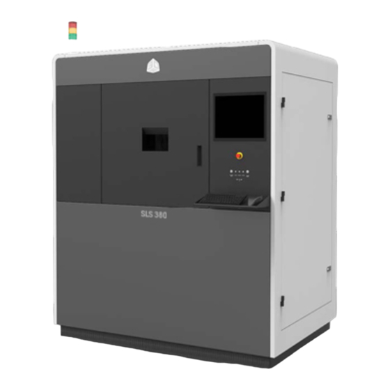
- Page 23 The SLS 380, the new cutting-edge SLS production 3D printer from 3D Systems, takes SLS toughness, part quality, and manufacturing economics to the next level. Designed for smooth integration with your manufacturing work ow, the SLS 380 produces parts for a variety of end-use and functional prototyping applications in aerospace, medical, industrial design, and more.
- Page 24 8/11/22, 4:33 PM User Guide Stack Light - Indicates the state of the system. Process Chamber - There are two doors in front of the Print Chamber—the outer locking door, and the inner print chamber door. The parts are printed inside the Process Chamber. E-Stop - The Emergency Stop button is a safety mechanism used to shut off the machine in an emergency situation in which it cannot be shut down in the usual manner.
-
Page 25: Auxiliary Sls Equipment
8/11/22, 4:33 PM User Guide Auxiliary SLS Equipment There are several auxiliary components which can accompany the SLS 380 system. MQC 600 Single and 600 Flex The MQC (Material Quality Control) 600 Systems are designed to be used as a material handling unit for many 3D Systems SLS printers,... -
Page 26: Nitrogen Generator
This ensures that the laser assembly does not overheat. Nitrogen Generator The SLS 380 printer uses nitrogen gas to make the print chamber inert. 3D Systems manufactures a High-Performance Nitrogen Generator — Part Number 104011-02. The generator is ideal for SLS applications. -
Page 27: User Interface
8/11/22, 4:33 PM User Guide User Interface Click here to view the interactive overview! The User Interface, located on the front panel of the printer, consists of a monitor and the system status LED indicators. infocenter.3dsystems.com/sls-380/print/book/export/html/526 27/87... -
Page 28: Electrical Cabinet
8/11/22, 4:33 PM User Guide User Interface - The user controls the system using a keyboard and pointing device located below the monitor. Emergency Stop - This switch, located below the monitor, immediately disables all hazardous machine functions or renders them safe. -
Page 29: Part Transfer Cart Assembly
Part Transfer Cart Assembly The print cake Extraction Cylinder, Part Transfer Tray, and Part Transfer Cart are used to remove the print cake from the SLS 380 process chamber and transport it to an MQC 600 System. The system ships with the cylinder and tray. The transfer cart is optional. - Page 30 8/11/22, 4:33 PM User Guide Light Color Solid Flashing E-Stop System fault active Normal Condition Yellow System is System warning active and/or E-Stop in service message present on condition mode touchscreen or normal Green Print job System Active, not printing, E-Stop active manual operations possible...
- Page 31 8/11/22, 4:33 PM User Guide Infrared Sensor and Black Body (behind panel) - The infrared sensor reads the temperature of the part bed surface. Periodically during a build, the black body covers the IR sensor to provide a reference temperature against which to read the print bed temperature.
-
Page 32: System Requirements And Setup
Power on Printer Your 3D Systems certi ed installer should have powered on your system for you. However, if the system or any of its components have unexpectedly shut down, or if you have shut them down, this section describes how to start up the system's components. - Page 33 NOTE: 3D Sprint software is always subject to updates. An announcement, along with release notes, will accompany a new software-version release. NOTE: On the SLS 380 PC, automatic updates in 3D Sprint are disabled. 3D Sprint should only be updated on the printer PC after verifying the update is supported on the system.
- Page 34 8/11/22, 4:33 PM User Guide Click the icon in 3D Sprint for information on: Adding the SLS 380 printer Adding a virtual printer Removing a printer Choosing a printer for a print job Updating rmware 3D Connect This printer is 3D Connect capable. For more information on 3D Connect architecture, security and requirements, please see the following link: https://www.3dsystems.com/software/3d-connect...
-
Page 35: System Operations
This section gives an overview of the part printing process. The software used to print parts on the SLS 380 printer consists of the 3D Sprint and Sinter applications. 3D Sprint is used to prepare models for printing. The models are then processed and transferred to the Sinter application which controls the printing of the parts. -
Page 36: Messages In The Sinter Application
8/11/22, 4:33 PM User Guide Messages in the Sinter Application When Sinter is running, various types of messages appear in the Message List window (described below). Alarm and warning messages also appear in pop-up windows you must clear in Windows. Alarm example Type Color De nition... -
Page 37: Viewing A Build In Progress
8/11/22, 4:33 PM User Guide Viewing a Build in Progress During a build, the Build Viewer window displays the slice that the system is currently scanning. Click on a part to display its name at the bottom of the main window. NOTE: If you close the Build Viewer window when a build is not running, you exit Build mode. -
Page 38: Pausing A Build
8/11/22, 4:33 PM User Guide Pausing a Build When the Pause Build button is active, click on it to pause the build and display options. When pausing a build, use the following guidelines: 1. If planning on pausing the build, plan out all actions you wish to take ahead of time so the pause will be as short as possible. -
Page 39: Adding And Deleting Parts And Other Changes
8/11/22, 4:33 PM User Guide You can make changes during a build with the Roll over to zoom. Build Modify dialog box. To display it, click the Change Parameter button; if the build is paused, click the Change Pro les/Prime Cycle button in the Pause Build dialog box. -
Page 40: When A Build Ends
8/11/22, 4:33 PM User Guide The Prime Cycle can only be run if the user has paused the build. Click the Prime Cycle button in the Build Modify dialog to spread powder across the print bed without moving the part piston, which can compensate for a short feed. -
Page 41: Manual Operations
8/11/22, 4:33 PM User Guide Print - Click to send the build time report to a printer on your network. Launch LogManager - Click to open a more-detailed summary of the build. Manual Operations The Manual Operations (Man Ops) section of the Sinter application provides access to several components of the printer which need to be controlled manually while operating the system. -
Page 42: Adding And Leveling Powder
8/11/22, 4:33 PM User Guide 1. To home the piston, click the Home Limit button in the Piston Control window. 2. After the piston is homed, click the Start Position button to bring the piston to build-start position. Home the Roller To home the roller, click the Home Limit button in the Roller Control window. - Page 43 8/11/22, 4:33 PM User Guide NOTE: Click the Stop button if you need to stop the roller while it is adding a layer. If you do this, you must move the roller back to its right or left limit before continuing. Click the Move To Limit button to move the roller back to a limit.
-
Page 44: Calibrating The Ir Sensor
8/11/22, 4:33 PM User Guide Parameter Range Default De nition Layer 0.1 mm 0.1 mm The distance that the part piston Thickness (0mm lowers each layer. available Powder Layer) Layer Cycle 1 and The number of consecutive Count 32,000 powder layers to be added. - Page 45 8/11/22, 4:33 PM User Guide You must perform an initial o ine IR calibration to enable automatic, real-time recalibration during the print. If recalibration requires too great an adjustment, a message pops up advising you to perform o ine calibration again when the print completes. To perform manual calibration, perform the following steps: Before beginning, verify that black body...
- Page 46 8/11/22, 4:33 PM User Guide NOTE: During the calibration, an Abort button appears; click it if you need to stop the calibration process for any reason. NOTE: If the part bed or the blackbody is above 60°C, the software waits until they cool to actually start the o ine calibration.
- Page 47 8/11/22, 4:33 PM User Guide Software Steps Before Every Print Prepare 3D Sprint Build Packet (link) Final Checks (link) Daily - Before Every Print Process chamber maintenance (link) Check N and air regulator settings (link) Verify coolant ow is 6 lpm and chiller set to 20°C (link) Verify Blended Bin powder level, or that MQC can blend during build (link) Empty Transporter (Sock) Filter on printer (link) and on MQC (link) Inspect and clean black body (link)
-
Page 48: Preparing A Print Job Using 3D Sprint
Preparing a Print Job Using 3D Sprint 3D Sprint is 3D Systems’ exclusive software for importing CAD data and preparing it for printing. 3D Sprint can be used either on the SLS 380, remotely connected from your workstation, or off-line at a stand-alone workstation (Virtual Printer). -
Page 49: Run Sinter Application
The 3D Sprint application contains extensive help with further details pertaining to the operation of the software. To prepare a print job on the SLS 380, you will need to do the following: 1. Run Sinter. 2. Launch 3D Sprint. - Page 50 Prepare 3D Sprint Build Packet The 3D Sprint Help menu offers full documentation for preparing build les and modifying build parameters for SLS 380 print jobs. To access the documentation: 1. In 3D Sprint, click the icon in the upper-right- hand corner of the screen.
-
Page 51: Final Checks
8/11/22, 4:33 PM User Guide 2. This will open up 3D Sprint Help in your default web browser. Use either the left-hand navigation or the search function to nd the information you are seeking. Final Checks Quality Check Run this to check for: Collisions Wall Thickness Other part quality issues... -
Page 52: Running The Build
8/11/22, 4:33 PM User Guide Add to Queue - creates a build packet le (.bpf) and associated les that will be used by Sinter to process the print job. Print to File - creates a compressed zip le (.bpz) that contains the bpf and associated les. This le may be added to the Queue at a later date or transferred to another SLS machine for processing. - Page 53 8/11/22, 4:33 PM User Guide Lab-grade ethanol (preferred) or isopropyl alcohol 2.5 mm Allen wrench Soft brush CAUTION: Before beginning any of the procedures in this section, make sure that the printer has cooled down to 70°C to prevent burn hazards. CAUTION: Do not clean process chamber with compressed dry air, as: 1.
- Page 54 8/11/22, 4:33 PM User Guide . Inspect and clean chamber door seal. If seal is damaged, contact 3D Systems Service. Otherwise, wipe down the door seal with a lint free cloth and IPA or Ethanol. 7. Pull the pull pins up to lift up the Heater Trays.
- Page 55 8/11/22, 4:33 PM User Guide 10. Clean the roller. 11. Wipe the process chamber walls with a tack cloth. 12. Clean under the roller. To see the over ow on left, the powder chute must be lifted manually. a. Close the inner and outer process chamber doors. b.
- Page 56 8/11/22, 4:33 PM User Guide e. Brush material in the area that had been covered by the roller into the over ow, and then clean the area with a non-ignition vacuum cleaner and tack cloth. 13. Clean the belt seals. infocenter.3dsystems.com/sls-380/print/book/export/html/526 56/87...
- Page 57 IPA. There are two light bulbs located on the heater assembly. If one or both of them burns out, contact 3D Systems Service. 15. Clean the part piston and around the part piston seals. 1 . Clean the laser window.
- Page 58 8/11/22, 4:33 PM User Guide 1. Verify the printer’s compressed air supply. a. Verify that facility compressed air is on and connected to the gauge panel AIR INLET. b. The air pressure gauge label indicates the correct reading. This should be: 350 KPa (51 psi). 2.
- Page 59 8/11/22, 4:33 PM User Guide 1. The gauge to check the coolant ow is on the lower-left side of the printer, as shown at the right. Verify that this reads at least 6 lmp. 2. Verify that the coolant temperature in the chiller is 20°C.
- Page 60 8/11/22, 4:33 PM User Guide Verify Printer's Material Supply Verify the material supply using either of the following two ways: In Sinter, check the MQC 600 System’s window in the Man Ops screen. This displays the MQC 600 System’s status, including the amount of available powder, or...
- Page 61 8/11/22, 4:33 PM User Guide . Press the Layer button on the toolbar to create a level print bed: NOTE: While the machine is becoming inert, begin leveling powder. Set the Layer Thickness to 0.0. Specify the number of cycles, normally 15-20 at a minimum. In the Layer Cycle Count eld, press the Add Layer button to begin leveling.
- Page 62 8/11/22, 4:33 PM User Guide 3. Raise heaters. 4. Remove the Laser Window Ba e by turning it counterclockwise ¼-turn and pulling down. Put it in a safe, clean location and clean the lens before reinstalling it in the process chamber. 5. Push the Laser Window Plug into the Window Hole. infocenter.3dsystems.com/sls-380/print/book/export/html/526 62/87...
- Page 63 8/11/22, 4:33 PM User Guide . With the handle facing toward you, fully insert the extraction cylinder into the process chamber, placing it over the print bed. CAUTION: Make sure the outer tabs of the cylinder catch on the rim of the process chamber door (see below).
- Page 64 8/11/22, 4:33 PM User Guide 9. Once the piston has nished raising the print cake, open the outer and inner process chamber doors. 10. Slide the Print Cake Tray underneath the cylinder, as shown, and latch the tray with the pull pins on the cylinder (see below).
- Page 65 8/11/22, 4:33 PM User Guide 12. Move the Part Transfer Cart into alignment with process chamber. 13. Slide the cylinder and tray out of the chamber and onto the cart. 14. If you cooled the parts in the printer, you may now break out your parts.
- Page 66 8/11/22, 4:33 PM User Guide 1. Immediately after placing the hot print cake in the breakout area of the MQC, you can optionally place the nitrogen cooling lid onto the print cake cylinder. The lid provides an oxygen- free environment for the print cake, protecting mechanical properties and part color.
-
Page 67: Regular Maintenance
8/11/22, 4:33 PM User Guide Regular Maintenance Clean the Laser Window Frequency Daily The laser beam passes through the laser window into the process chamber. It is very important that all impurities are kept off the laser window. Impurities can be burned onto the laser window, decreasing the laser power available at the print bed. - Page 68 8/11/22, 4:33 PM User Guide 2. Bring the laser window ba e to a clean area and set it down on a clean cloth (1) as shown. When not in use or being cleaned, cover it with lens tissue and secure the tissue over the lens using the tissue box (2).
- Page 69 8/11/22, 4:33 PM User Guide 4. Cover the lens with a lens tissue, and turn the assembly over so that the lens comes out. Carefully set the lens aside on your work table. 5. Remove the O-Ring from the lens and wipe the o- ring clean with a lens cloth.
- Page 70 8/11/22, 4:33 PM User Guide . OPTIONAL - Bring the lens to an area where it can be cleaned with mild soap (such as dish soap) and warm water. Soap will get sticky residue off the lens before the nal cleaning with ethanol in future steps. Have lens cloths ready.
- Page 71 8/11/22, 4:33 PM User Guide 12. Apply a small amount of ethanol to the lens again and fold up a lens tissue lengthwise. 13. Gently pull the tissue across the lens. 14. Fold the same tissue once again and gently wipe once more.
- Page 72 8/11/22, 4:33 PM User Guide 17. Place the housing ring on top the assembly, ensuring that you still see the o-ring underneath. The lens should also be ush with the housing ring. Fasten the ring using the screws that were set aside earlier using a 2.5mm Allen wrench. Use the long end of the Allen wrench to prevent over- tightening.
- Page 73 8/11/22, 4:33 PM User Guide 19. Remove the laser window plug. 20. Insert the laser window ba e into the recess at the top of the process chamber, with the warning label facing slightly to the left. Rotate the ba e clockwise one quarter turn to tighten it in place. The heat-warning label should be facing straight forward when the ba e is fully tightened.
- Page 74 8/11/22, 4:33 PM User Guide 1. Remove the right-side panel to expose the black body. Remove the three screws from the black body cover. 2. Remove the metal black body bracket. 3. Remove the white black body cover. → infocenter.3dsystems.com/sls-380/print/book/export/html/526 74/87...
- Page 75 8/11/22, 4:33 PM User Guide 4. Place a small amount of ethanol on an SLS IR sensor cleaning swab (part #4100-01431). 5. Gently rub the swab in a back-and-forth motion to clean the blackbody. . Use a dry swab to dry the blackbody. Repeat until clean.
- Page 76 Clean and Replace Filters There are several lters on the SLS 380 that need to be cleaned or replaced periodically. It is suggested that each of them be checked weekly and replaced as necessary:...
- Page 77 8/11/22, 4:33 PM User Guide 1. Open the upper-back doors of the printer, ensuring that the door interlock is unlocked. 2. Unscrew the thumb screws on the lter cover and remove the cover. 3. Vacuum in and around the exhaust chamber box.
-
Page 78: Electrical Enclosure Filter
8/11/22, 4:33 PM User Guide 7. To clean the exhaust port inside the process chamber, use a non-ignition vacuum cleaner to remove any debris that has accumulated. Electrical Enclosure Filter Frequency Every three months Air moving through the electrical cabinet is cleaned by the lter on the left-side door of the electrical enclosure. You can access the ... -
Page 79: Transporter Filter ( Sock Filter )
8/11/22, 4:33 PM User Guide 2. Remove and replace the lter. Ensure that the air ow arrow on the new lter points toward the machine on installation. 3. Reinstall the lter bracket with the four thumbscrews removed earlier. Transporter Filter ( Sock Filter ) Frequency Every six months The transport lter (sock lter) ... - Page 80 8/11/22, 4:33 PM User Guide 1. Open the lower-left door of the printer to expose the sock lter. 2. Loosen the top and bottom thumb screws to unclamp the sock lter. 3. Pull back on the sock lter tabs to remove the lter.
- Page 81 1. To test, move a piece of paper over the e-box lter, as shown. If the paper gets sucked toward the lter, the fan is operational. If the paper does not get sucked, contact 3D Systems Service. infocenter.3dsystems.com/sls-380/print/book/export/html/526 81/87...
- Page 82 8/11/22, 4:33 PM User Guide Shut Down the Printer To properly shut down the printer: 1. Run KillSinter.exe. 2. Shut down Windows. 3. Turn off the printer main power. 4. If power cycling the system, see the Power on Printer section for further instructions.
-
Page 83: Service And Support
UK and EMEA: +44 1442 279883 International: +1 803-326-3930 General SLS 380 service procedures must be performed only by a 3D Systems-certi ed service technician unless this guide explicitly states otherwise. If your SLS system needs service, contact 3D Systems Technical Support at the following numbers:... - Page 84 8/11/22, 4:33 PM User Guide You can also contact your local 3D Systems representative. 3D Systems’ support portal is located at http://www.3dsystems.com/support For safety data sheets of SLS materials, go to http://www.3dsystems.com/support/materials/msds infocenter.3dsystems.com/sls-380/print/book/export/html/526 84/87...
-
Page 85: Ec Declaration Of Conformity
8/11/22, 4:33 PM User Guide EC Declaration of Conformity infocenter.3dsystems.com/sls-380/print/book/export/html/526 85/87... - Page 86 8/11/22, 4:33 PM User Guide infocenter.3dsystems.com/sls-380/print/book/export/html/526 86/87...
- Page 87 8/11/22, 4:33 PM User Guide © 2022 by 3D Systems, Inc. All rights 3D Systems, Inc. reserved. Speci cations subject to 333 Three D Systems Circle | Rock Hill, SC | change without notice. 3D Systems, 29730 the 3D Systems logo, ProX, and www.3dsystems.com...
Need help?
Do you have a question about the SLS 380 and is the answer not in the manual?
Questions and answers