Graco A Series Instructions - Parts Manual
Air motors
Hide thumbs
Also See for A Series:
- Instructions - parts manual (52 pages) ,
- Instructions-parts list manual (48 pages) ,
- Manual (36 pages)
Table of Contents
Advertisement
Quick Links
Instructions/Parts
SaniForce
For use on SaniForce
fluids in applications requiring high sanitation. For professional use only.
Model 24G785, Series A, 3.5 in. Air Motor
Model 24G786, Series A, 6.0 in. Air Motor
Model 24G787, Series A, 7.5 in. Air Motor
Model 24R491, Series A, 6.0 in. Air Motor
Model 24R015, Series A, 7.5 in. Air Motor
Model 24W754, Series A, 6.0 in. Air Motor
Important Safety Instructions
Read all warnings and instructions in this manual.
For complete warnings and instructions see your
pump or package manual. Hazard symbols refer to
specific procedure risks. Save all instructions.
See page 5 for model information, including maximum
air inlet pressure.
.
™
Air Motors
™
piston pumps, which are used to transfer medium to high viscosity
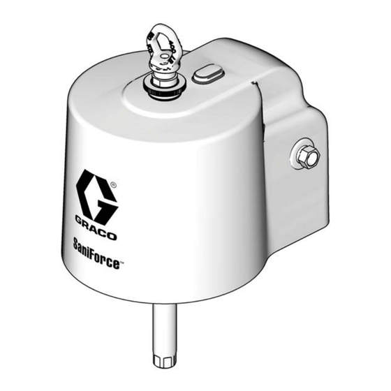
Air Motor shown with
Shrouds and Lift Ring
(see page 5)
3A1211N
EN
ti16220a
Advertisement
Table of Contents

Related Manuals for Graco A Series


Summary of Contents for Graco A Series
- Page 1 Instructions/Parts ™ SaniForce Air Motors 3A1211N ™ For use on SaniForce piston pumps, which are used to transfer medium to high viscosity fluids in applications requiring high sanitation. For professional use only. Model 24G785, Series A, 3.5 in. Air Motor Model 24G786, Series A, 6.0 in.
-
Page 2: Table Of Contents
Repair Air Valve ......9 Graco Standard Warranty ....22 Replace Pilot Valves . -
Page 3: Warnings
Warnings Warnings The following warnings are for the setup, use, grounding, maintenance, and repair of this equipment. The exclama- tion point symbol alerts you to a general warning and the hazard symbol refers to procedure-specific risk. When these symbols appear in the body of this manual, refer back to these warnings. Additional, product-specific warnings may be found throughout the body of this manual where applicable. - Page 4 Warnings WARNING EQUIPMENT MISUSE HAZARD Misuse can cause death or serious injury. • Do not operate the unit when fatigued or under the influence of drugs or alcohol. • Do not exceed the maximum working pressure or temperature rating of the lowest rated system component.
-
Page 5: Models
Models Models Check your motor’s identification plate (ID) for the 6-digit part number of your motor. ti16228a Air Motor Air Motor Piston Part in Kit with Displacement Stroke Diameter, Maximum Air Inlet Pressure Number Shrouds Series (cc per cycle) (in.) in. -
Page 6: Component Identification
Lift Ring Upper Shroud See F . 1. Connect a ground wire (Graco PN 238909) Lower Shroud (out of view) to the ground screw (12) on the bottom cover of the air motor, under the shroud. Connect the other end of the ground wire to a true earth ground. -
Page 7: Troubleshooting
Troubleshooting Troubleshooting NOTE: Check all possible problems and causes before disassembling the pump. Relieve the pressure before checking or servicing the equipment. Problem Cause Solution Air motor will not run. Damaged air valve (17). Replace or service air valve (17). See page 9. -
Page 8: Repair
Repair Repair Preventive Maintenance Schedule The operating conditions of your system determine how often maintenance is required. Establish a preventive maintenance schedule by recording when and what kind of maintenance is needed, and then determine a regular schedule for checking your system. Pressure Relief Procedure •... -
Page 9: Repair Air Valve
Repair Repair Air Valve Replace Complete Air Valve Disassemble the Air Valve 1. Perform steps 1-4 under Replace Complete Air 1. Stop the pump at the middle of its stroke. Follow Valve, page 9. Pressure Relief Procedure, page 8. 2. See F . - Page 10 Repair Reassemble the Air Valve 110 1. Lubricate detent cam (104) and install into hous- ing. 106† 2. Lubricate the u-cups (108†) and install on the pis- 107 ton (102) with lips facing toward the center of the piston. 108† 104...
-
Page 11: Replace Pilot Valves
Repair 112 Magnet ti12752a . 6. Air valve cup installation 8. Install the valve plate (105). Tighten the screws (109†) to hold it in place. Replace Pilot Valves 1. Stop the pump at the middle of its stroke. Follow Pressure Relief Procedure, page 8. 2. -
Page 12: Repair Air Motor
Repair Repair Air Motor Reassemble the Air Motor NOTE: Use NLGI No 1, bentone-based grease for lubri- cant. Exception: Use appropriate sanitary lubricant for the center grommet in the bottom shroud. NOTE: Air Motor Seal Kits are available. See page 17 NOTE: For easier reassembly, start with the top cover for the correct kit for your motor. -
Page 13: Attach The Shroud
Repair 9. Carefully place the bottom cover (1) on the cylinder Attach the Shroud (11), sliding the rod through the bearing. The mani- fold surfaces of the top and bottom covers must 1. Inspect the grommets on the top and bottom align. -
Page 14: Parts
Parts Parts Air Motor Kit, plus Lift Ring, Fittings, Shrouds, and Fasteners 16* ti116225b Torque varies by motor size: Model 24G785: 11-13 ft-lb (15-18 N•m) Models 24G786, 24G787, 24R015, 24R491: 25-30 ft-lb (34-40 N•m) Apply NLGI No. 1, bentone-based grease. U-cup faces up. -
Page 15: Air Motor Parts - All Models
Parts Air Motor Parts — All Models (See page 16 for Shroud Kits, Fittings, and Fasteners, sold separately.) Model Model Model Model Model Model Ref. Description 24G785 24G786 24R491 24G787 24R015 24W754 24A545 24A549 24A553 24A549 COVER, lower, assembly; includes Refs. -
Page 16: Shroud Kits, Fittings, And Fasteners
Parts Model Model Model Model Model Model Ref. Description 24G785 24G786 24R491 24G787 24R015 24W754 16T537 16T537 16V087 16T537 16G523 16G523 ADAPTER; includes Ref. 32 110636 110636 110782 110636 110782 110782 O-RING, for adapter Not sold separately. See Air Motor Seal Kit (page 17) or SEAL, u-cup with flange Lower Cover Assembly (Ref. -
Page 17: Air Motor Seal Kits
Parts Air Motor Seal Kits Model 24A352 Air Valve Parts Air Motor Model Air Motor Seal Kit 110 24G785 16G524 106† 24G786, 24A547 24R491, or 107 24W754 24G787 or 24A551 24R015 104 103 111 112 105 108† 102 109† 108† 107... -
Page 18: Air Valve Kits
Parts Air Valve Kits NOTE: Air valve parts are not sold individually. The table below shows possible kit options for each part. Air Valve Air Valve Air Valve Repair Kit Seal Kit End Cap Kit Ref. Description Qty. 24A538 24A536 24A361 Other HOUSING... -
Page 19: Dimensions
Dimensions Dimensions Air Motor Weight Model inch (mm) inch (mm) inch (mm) inch (mm) inch (mm) lb (kg) 24G785 13.7 (348) 16.3 (414) 10.0 (254) 7.7 (196) 9.2 (234) 12.0 (5.4) 24G786 14.5 (368) 18.8 (478) 14.2 (361) 10.9 (277) 11.0 (279) 26.0 (11.8) 24G787 14.5 (368) - Page 20 Dimensions 3A1211N...
-
Page 21: Technical Data
Technical Data Technical Data Maximum air inlet pressure ..... . . 100 psi (0.7 MPa, 7.0 bar) Stroke length ........4.75 in. Air inlet size . -
Page 22: Graco Standard Warranty
With the exception of any special, extended, or limited warranty published by Graco, Graco will, for a period of twelve months from the date of sale, repair or replace any part of the equipment determined by Graco to be defective.
Need help?
Do you have a question about the A Series and is the answer not in the manual?
Questions and answers