Graco A Series Instructions - Parts Manual
Plural component, impingement mix mechanical purge spray gun
Hide thumbs
Also See for A Series:
- Instructions-parts list manual (48 pages) ,
- Manual (36 pages) ,
- Repair instructions (34 pages)
Table of Contents
Advertisement
Quick Links
Instructions-Parts
309856A
Plural Component, Impingement Mix
Mechanical Purge Spray Gun
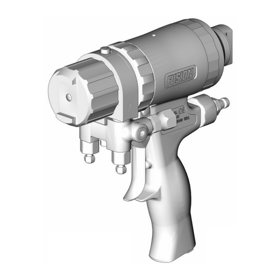
For use with non-flammable foam and polyurea.
Not for use in explosive atmospheres.
3500 psi (24.2 MPa, 242 bar) Maximum Fluid Working Pressure
80-130 psi (0.55-0.9 MPa, 5.5-9.1 bar) Air Inlet Pressure Range
200 ° F (94 ° C) Maximum Fluid Temperature
TI3840a
US Patent Pending
Graco Inc. P.O. Box 1441 Minneapolis, MN 55440-1441
Copyright 2003, Graco Inc. is registered to I.S. EN ISO 9001
Advertisement
Table of Contents

Related Manuals for Graco A Series


Summary of Contents for Graco A Series
- Page 1 80-130 psi (0.55-0.9 MPa, 5.5-9.1 bar) Air Inlet Pressure Range 200 ° F (94 ° C) Maximum Fluid Temperature TI3840a US Patent Pending Graco Inc. P.O. Box 1441 Minneapolis, MN 55440-1441 Copyright 2003, Graco Inc. is registered to I.S. EN ISO 9001...
-
Page 2: Table Of Contents
Clean Outside of Gun ....21 Graco Information ......52 Clean Air Cap . -
Page 3: Manual Conventions
Manual Conventions Manual Conventions Warning Caution CAUTION WARNING A caution alerts you to possible equipment damage or destruction if you do not follow instructions. Note A warning alerts you to possible serious injury or death if you do not follow instructions. A note indicates additional helpful information. -
Page 4: List Of Models/Selection Guide
List of Models/Selection Guide List of Models/Selection Guide Standard Round Pattern Guns Use only these mix module/tip combinations. Gun Part No., Series Polycarballoy Mix Module Part No., Round CeramTip Part No., see page 44 for numbering code see page 46 for numbering code 247211, A MR3535 RTM030... -
Page 5: Standard Flat Pattern Guns
List of Models/Selection Guide Standard Flat Pattern Guns Use only these mix module/tip combinations. Gun Part No., Series Polycarballoy Mix Module Part No., Flat CeramTip Part No., see page 44 for numbering code see page 46 for numbering code 247257, A MF1818 FTM317 247258, A... -
Page 6: Direct Impingement Round Pattern Guns
List of Models/Selection Guide Direct Impingement Round Pattern Guns Use only these mix module/tip combinations. Gun Part No., Series Polycarballoy Mix Module Part No., Round CeramTip Part No., see page 44 for numbering code see page 46 for numbering code 247006, A XR2929 RTM030... -
Page 7: Direct Impingement Flat Pattern Guns
List of Models/Selection Guide Direct Impingement Flat Pattern Guns Use only these mix module/tip combinations. Gun Part No., Series Polycarballoy Mix Module Part No., Flat CeramTip Part No., see page 44 for numbering code see page 46 for numbering code 247050, A XF1313 FTM317... -
Page 8: Warning
Warning WARNING PERSONAL PROTECTIVE EQUIPMENT You must wear proper protective equipment when operating, servicing, or when in the operating area of the equipment to help protect you from serious injury, including eye injury, inhalation of toxic fumes, burns, and hearing loss. This equipment includes but is not limited to: •... - Page 9 Misuse can cause serious injury or death. • For professional use only. • Use equipment only for its intended purpose. Call your Graco distributor for information. • Read manuals, warnings, tags, and labels before operating equipment. Follow instructions. • Check equipment daily. Repair or replace worn or damaged parts immediately.
-
Page 10: Overall View
Overall View Overall View TI3840a-1 Key: A Side Fluid Valve (ISO) Cleanoff Air Valve B Side Fluid Valve (RESIN) Safety Lock Air Cap CeramTip (behind air cap) Air Line Quick Coupler Optional Fluid Inlets (A Side Shown) Muffler Lock Ring Fluid Housing Fluid Inlet Swivels (A Side Shown) Gun Fluid Manifold... -
Page 11: Isocyanate Hazard
Read warnings, page 9. lock. Check your local electrical code and proportioner man- ual for detailed grounding instructions. • Close fluid valves A and B. Ground the spray gun through connection to a Graco-approved grounded fluid supply hose. TI3837a 309856A... -
Page 12: Setup
Setup Setup Close fluid valves A and B. Connect gun air whip hose (T) and air valve (U) to main air hose. Attach fluid manifold (G) to gun. TI2411A Connect A (ISO) and B (RESIN) fluid hoses to fluid TI3830a manifold. - Page 13 Setup Open B (RESIN) fluid valve (about three half Test spray onto cardboard. Adjust pressure and turns). Then open A (ISO) fluid valve. temperature to get desired results. TI3861a Apply layer of lubricant over front of gun and lock TI3838a ring, or use gun cover to prevent overspray buildup and ease disassembly.
-
Page 14: Adjust Purge Rod
Adjust Purge Rod Adjust Purge Rod Engage safety lock, page 11. Connect air supply and open air valve (U). Adjust purge rod with nut driver clockwise until it just touches CeramTip, then back off 1/8-1/4 turn. TI3850a 1/8-1/4 Turn Close fluid valves A and B. TI3829a TI3828a Be sure to back out purge rod 1-2 turns before... -
Page 15: Adjust Flat Ceramtip
Adjust Flat CeramTip Adjust Flat CeramTip WARNING Remove air cap (9). Read warnings, page 8. Engage safety lock, page 11. TI3854a TI3850a Using nut driver, position CeramTip as desired. Close fluid valves A and B. TI3867a Reassemble air cap (9) fingertight. TI3837a 309856A... -
Page 16: Shutdown
Shutdown Shutdown Daily Shutdown Shutdown for More than a Follow Pressure Relief Procedure, page 17. Flush Gun, page 21. Follow Pressure Relief Procedure, page 17. 309856A... -
Page 17: Pressure Relief Procedure
Pressure Relief Procedure Pressure Relief Procedure WARNING Trigger gun onto cardboard or into waste container to relieve pressure. Read warnings, page 8. Relieve pressure before cleaning or repairing gun. Engage safety lock, page 11. TI3861a Engage safety lock, page 11. TI3850a CAUTION Air supply is required for gun actuation. -
Page 18: Optional Configurations
Optional Configurations Optional Configurations Optional Fluid Manifold Unscrew lock ring (P) until front end of gun is Position loose. Fluid manifold is mounted to bottom of gun, with A side on left, viewed from operator’s position at back of gun. If Rotate fluid housing (F) 180°... -
Page 19: Optional Hose Position
Optional Configurations Optional Hose Position Apply thread sealant to plugs (W), elbows (V), and Fluid inlet swivels and air quick disconnect fitting point to male threads of swivels (A, B). Install elbows (V) in rear. If desired, these positions can be changed so optional inlets (N), facing down. -
Page 20: Maintenance
Maintenance Maintenance Supplied Tool Kit Clean Muffler, page 21. • Hex Nut Driver; 5/16 • Screwdriver; 1/8 blade Clean Fluid Manifold, page 21. • CeramTip Drill Bit; various sizes depending on CeramTip size. See T 2, page 24. ABLE Clean Polycarballoy Mix Module, page 22. •... -
Page 21: Flush Gun
Maintenance Flush Gun Clean Air Cap If it is necessary to flush gun, use following procedure. Soak air cap in compatible solvent. If necessary, clean gently with stiff brush. WARNING Clean Muffler Remove and clean muffler with compatible solvent. Read warnings, page 9. Clean Fluid Manifold Follow Pressure Relief Procedure, page 17. -
Page 22: Clean Polycarballoy Mix Module
Maintenance Clean Polycarballoy Mix Module Follow Pressure Relief Procedure, page 17. Flush Gun, page 21. TI3863a . 1. Cleaning Component A (ISO) Ports Remove Polycarballoy Mix Module, page 36. CAUTION To avoid damaging Polycarballoy Mix Module, do not force drill bits when cleaning impingement ports. Some ports are offset or angled. - Page 23 Maintenance Table 1: Impingement Port Cleanout Drill Sizes Standard Round Polycarballoy Mix Modules Polycarballoy No. of Impingement Port Drill Counterbore Drill Mix Module Impinge- Drill Size Drill Diameter Drill Size Drill Diameter Part No. ment Ports (nominal) in. (mm) (nominal) in.
-
Page 24: Clean Ceramtip
Maintenance Clean CeramTip Round CeramTip Flat CeramTip Follow Pressure Relief Procedure, page 17. Follow Pressure Relief Procedure, page 17. Remove CeramTip, page 32. Remove CeramTip, page 32. Clean CeramTip with appropriate size drill (sup- Soak CeramTip in compatible solvent. If neces- plied). -
Page 25: Stuck Purge Rod
Maintenance Stuck Purge Rod Disconnect air (D) and remove fluid manifold (G). If purge rod (31) is stuck and cannot actuate, use this procedure to free it. Engage safety lock, page 11. TI3837a TI3850a Disassemble Front End, page 33. Trigger gun and hold. Turn purge rod counterclock- wise. -
Page 26: Adjust Front Rod Seal
Maintenance Adjust Front Rod Seal Remove air cap (9). If fluid misting occurs from tip when gun is not triggered, use following procedure to temporarily stop leakage until parts are replaced. Follow Pressure Relief Procedure, page 17. Back out purge rod 1-2 turns with nut driver. TI3854a Trigger gun and hold. -
Page 27: Adjust Rear Rod Seal
Maintenance Adjust Rear Rod Seal Remove fluid housing (7) from rod (31). Follow Pressure Relief Procedure, page 17. Reassemble Front End, page 34. Flush Gun, page 21. Adjust Purge Rod, page 14. Remove fluid manifold (G). Leave air connected. Attach fluid manifold. Return gun to service. TI3852a Disassemble Front End, page 33. -
Page 28: Troubleshooting
Troubleshooting Troubleshooting Follow Pressure Relief Procedure, page 17, before checking or repairing gun. Check all possible problems and causes before disassembling gun. CAUTION To prevent cross-contamination of the gun’s wetted parts, do not interchange A component (isocyanate) and B component (resin) parts. PROBLEM CAUSE SOLUTION... - Page 29 Troubleshooting PROBLEM CAUSE SOLUTION Loss of round pattern. Dirty CeramTip (40). Clean, page 24. Loss of flat pattern. Plugged CeramTip (40). Clean in compatible solvent. Worn CeramTip (40). Replace, page 32. Pressure imbalance. Plugged impingement ports. Clean, page 22. Reinstall Polycarbal- loy Mix Module, page 36.
-
Page 30: Theory Of Operation
Troubleshooting Theory of Operation Gun Triggered (Fluid Spraying) Gun Detriggered (Mechanical Purging) Purge rod (31) moves back, opening impingement ports Purge rod (31) moves forward, closing impingement (IP). Components A and B combine in Polycarballoy Mix ports (IP) and shutting off fluid flow. Rod pushes through Module (39). -
Page 31: Cutaway View
Troubleshooting Cutaway View 28 25 309856A... -
Page 32: Repair
Repair Repair Tools Required Back out purge rod 1-2 turns with nut driver. Tools needed for complete gun repair: • adjustable wrench • flat head screwdriver (included) • channel-lock pliers (2 pair) • 5/16 hex nut driver (included) • o-ring pick •... -
Page 33: Disassemble Front End
Repair Disassemble Front End Remove mix module nut (25), using air cap (9) or a wrench. Remove front seal (46). WARNING Read warnings, page 8. Proper attachment of front end is critical. Do not operate gun if front end is loose or lock ring is not snug against handle. -
Page 34: Reassemble Front End
Repair Reassemble Front End CAUTION To prevent damage to purge rod (31), always slide front end straight onto purge rod. Check that o-rings (20, 21) are in position. Liberally lubricate o-rings, threads of lock ring (11) and han- dle (1), and outside of lock ring. Carefully slide front end onto purge rod (31). - Page 35 Repair CAUTION Reinstall CeramTip (40). Lubricate all threads. Do not overtighten mix module nut (25). Overtighten- Install retainer (28) fingertight, plus 1 notch. Install ing can deform impingement holes. air cap (9) fingertight. Lubricate all threads and reassemble mix module nut (25) fingertight.
-
Page 36: Polycarballoy Mix Module
Repair Polycarballoy Mix Module Push new Polycarballoy Mix Module (39) onto rod See page 44 for available Polycarballoy Mix Module (31) as far as possible. sizes. Follow Pressure Relief Procedure, page 17. Flush Gun, page 21. TI3845a Remove fluid manifold (G). Leave air connected. WARNING Keep fingers away from mix module (39) when doing step 7. -
Page 37: Rod Seals
Repair Rod Seals Reassemble new rear seal (46) in rear rod seal nut (23). Lubricate threads and install in fluid housing (7) with nut driver. Follow Pressure Relief Procedure, page 17. Reassemble Front End, page 34. Flush Gun, page 21. Adjust Purge Rod, page 14. -
Page 38: Check Valves
Repair Check Valves Slide filter (36d) off. Clean and inspect parts. Thor- oughly inspect o-rings (36f, 36g). Replace if any Before disassembling, press on ball (36c) to test damage is seen, or external leakage may result. If check valve for proper movement and spring necessary, remove screw (36b) and disassemble action. -
Page 39: Piston And Purge Rod
Repair Piston and Purge Rod Pull purge rod to remove piston (32). Inspect piston o-ring (16) and shaft o-ring (19). Follow Pressure Relief Procedure, page 17. Flush Gun, page 21. Disconnect air (D) and remove fluid manifold (G). TI3846a Inspect purge rod (31) for scratches or damage. Unscrew rod from piston with nut driver. - Page 40 Repair Install safety lock assembly. Reassemble Front End, page 34. Adjust Purge Rod, page 14. Attach fluid manifold. Connect air. Return gun to TI3847a service. 309856A...
-
Page 41: Safety Lock
Repair Safety Lock Air Valve Follow Pressure Relief Procedure, page 17. Follow Pressure Relief Procedure, page 17. Flush Gun, page 21. Flush Gun, page 21. Disconnect air (D) and remove fluid manifold (G). Disconnect air (D) and remove fluid manifold (G). TI3837a TI3837a Unscrew safety lock assembly. -
Page 42: Parts
Parts Parts 25 39 †‡ 8 31 Supplied Tools ‡ ‡ ‡ †‡ ‡ ‡ TI3870a ‡ †‡ Flush Manifold Detail †‡ ‡ ‡ ‡ *36g ‡ TI2647a †‡ *36f †‡ ‡ † †‡ TI3851a Torque to 125-135 in-lb (14-15 N•m). Torque to 20-30 in-lb (2.3-3.4 N•m). - Page 43 Parts Ref. Ref. Part No. Description Part No. Description 246730 VALVE, check, A side; includes ‡ 248002 HANDLE 36a-36g 15B208 PLUG, air valve 234027 VALVE, check, B side; includes 15C374 ACTUATOR; safety 36a-36g 15C390 BUSHING, safety . HOUSING ‡† 203953 SCREW; 10-24 x 3/8 in. (10 mm) 1 15B214 .
-
Page 44: Polycarballoy Mix Module Kits
Parts Polycarballoy Mix Module Kits Polycarballoy Mix Module Part Numbering Code Example First Two Digits Second Two Digits Last Two Digits Part No. MR3535 MR=Mechanical purge standard, round pattern 35=Component A 35=Component B impingement port impingement port MF3535 MF=Mechanical purge standard, flat pattern size (.035 in.).*** size (.035 in.).*** XR3535... - Page 45 Parts Direct Impingement Round Pattern Guns Polycarballoy Mix No. of Impingement Module Kit Impingement Port Drill Bit (includes drill bits) Ports Size, nominal** XR2929 XR3535 XR4747 XR5757 Direct Impingement Flat Pattern Guns Polycarballoy No. of Impingement Counterbore Mix Module Kit Impingement Port Drill Bit Drill Bit Size,...
-
Page 46: Ceramtip Kits
Parts CeramTip Kits Round CeramTip Part Numbering Code Example First Three Digits Last Three Digits Part No. RTM055 RTM=Round CeramTip mechanical purge Equivalent orifice diameter size (.055 in.) Round CeramTips (include drill bit) CeramTip Part No. Drill Bit Size, nominal** RTM024 RTM030 RTM040... -
Page 47: Drill Bit Kits
Parts Drill Bit Kits For cleaning gun ports and orifices. Illustrations are actual size, for comparison. Not all sizes are used with your gun. Drill Bit Size Kit Part No. Qty in Kit Illustration nominal 246623 0.116 2.90 246810 7/64 0.109 2.77 246813... -
Page 48: Gun Repair Kits
Parts Gun Repair Kits Read the chart left to right and top to bottom to find the quantity of each part in the kits. Ref. 246351 246354 248000 248003 248095 248096 Check Valve O-ring Complete Purge Rod Purge Rod Piston Shaft O-ring Kit Multi-Kit O-ring Kit... -
Page 49: Accessories
Accessories Accessories Gun Cover Recirculation Manifold 244915 246362 Keeps gun clean while spraying. Pack of 10. Attach to gun fluid manifold to enable preheating of hose. See manual 309818. Lubricant 111265 Tube, 4 oz (113 gram) Sanitary, non-silicone lubricant for o-rings, threads, and wear areas. - Page 50 Accessories 309856A...
-
Page 51: Technical Data
Technical Data Technical Data Category Data Maximum Fluid Working Pressure 3500 psi (24.2 MPa, 242 bar) Minimum Air Inlet Pressure 80 psi (0.55 MPa, 5.5 bar) Maximum Air Inlet Pressure 130 psi (0.9 MPa, 9 bar) Maximum Fluid Temperature 200° F (94° C) Air Inlet Size 1/4 npt Quick Disconnect Nipple A Component (ISO) Inlet Size... -
Page 52: Graco Standard Warranty
Graco distributor to the original purchaser for use. With the exception of any special, extended, or limited warranty published by Graco, Graco will, for a period of twelve months from the date of sale, repair or replace any part of the equipment determined by Graco to be defective.
Need help?
Do you have a question about the A Series and is the answer not in the manual?
Questions and answers