Graco ULTRA MAX 1095 Instructions-Parts List Manual
Hide thumbs
Also See for ULTRA MAX 1095:
- Instructions and parts list (28 pages) ,
- Instruction manual (24 pages) ,
- Manual (24 pages)
Table of Contents
Advertisement
Quick Links
INSTRUCTIONS-PARTS LIST
This manual contains important
warnings and information.
READ AND KEEP FOR REFERENCE.
INSTRUCTIONS
120 VAC, 15A
ULTRA MAX 1095
AIRLESS PAINT SPRAYER
3000 psi (210 bar , 21 MPa ) Maximum Working Pressure
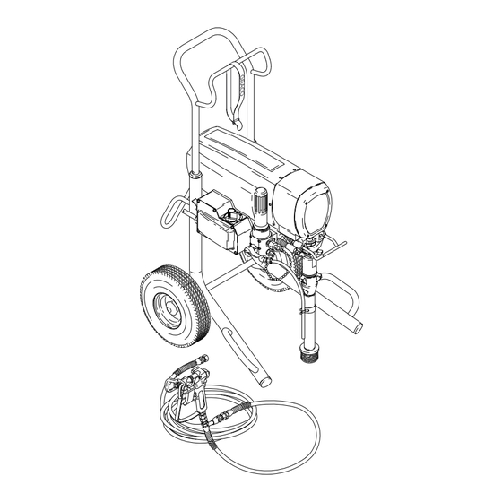
Model 232–150, Series A
Basic sprayer on Upright cart without
hose or gun
Model 232–151 Series A
Complete sprayer on Upright cart with hose,
gun, RAC IV
DripLess
and SwitchTip
U.S. PATENT NO. 4,323,741; 4,397,610
PATENTED 1983, CANADA
AND OTHER PATENTS PENDING
Related Manuals
Displacement Pump
. . . . . . . . . . . . . . . . . . . . . .
Spray Gun
. . . . . . . . . . . . . . . . . . . . . . . . . . . . . .
Spray Tip
. . . . . . . . . . . . . . . . . . . . . . . . . . . . . . . .
GRACO INC. P.O. BOX 1441 MINNEAPOLIS, MN 55440–1441
Tip Guard
308–798
308–645
308–644
http://www.graco.com
COPYRIGHT 1997, GRACO INC.
Graco Inc. is registered to I.S. EN ISO 9001
308–799
Supercedes Rev. A
First choice when
quality counts.
Rev. B
Advertisement
Table of Contents

Related Manuals for Graco ULTRA MAX 1095


Summary of Contents for Graco ULTRA MAX 1095
- Page 1 ....... . 308–644 GRACO INC. P.O. BOX 1441 MINNEAPOLIS, MN 55440–1441 http://www.graco.com COPYRIGHT 1997, GRACO INC. Graco Inc. is registered to I.S. EN ISO 9001...
-
Page 2: Table Of Contents
Read all instruction manuals, tags, and labels before operating the equipment. Use the equipment only for its intended purpose. If you are not sure, call your Graco distributor. Do not alter or modify this equipment. Use only genuine Graco parts. -
Page 3: Warnings
WARNING INJECTION HAZARD Spray from the gun, leaks or ruptured components can inject fluid into your body and cause extremely serious injury, including the need for amputation. Fluid splashed in the eyes or on the skin can also cause serious injury. Fluid injected into the skin is a serious injury. - Page 4 WARNING FIRE AND EXPLOSION HAZARD Improper grounding, poor ventilation, open flames or sparks can cause a hazardous condition and result in a fire or explosion and serious injury. If there is any static sparking or you feel an electric shock while using this equipment, stop spray- ing immediately.
-
Page 5: Component Function And Identification
Component Identification and Function Fig. 1 Motor DC motor, permanent magnet, totally enclosed, fan cooled Drive Assembly Transfers power from DC motor to the displacement pump Pail Hanger Container for fluid to be sprayed may be hung here Displacement Pump Transfers fluid to be sprayed from source through spray gun Primary Fluid Outlet Single spray gun operation is connected here... -
Page 6: Setup
See Fig. 1. WARNING NOTE: See Fig. 1, except where noted. 1. Fill packing nut full with Graco Throat Seal Liquid FIRE AND EXPLOSION HAZARD (TSL), supplied. Fig. 2. Proper electrical grounding is essential to reduce the risk of fire or explosion which can result in serious injury and property damage. -
Page 7: Startup
Setup Grounding Grounded Outlets WARNING Improper installation or alteration of the grounding Grounding Prong plug will result in a risk of electric shock, fire or Fig. 3 explosion that could cause serious injury or death. 2. Do not alter ground prong or use adapter. 3. - Page 8 Startup 7. Adjust spray pattern. RAC IV RETAINING HANDLE GUN SAFETY LATCH ENGAGED a. Increase pressure just until spray from gun is completely atomized. Use lowest pressure necessary to get desired results. This reduces overspray and fogging, decreases tip wear and extends the life of the sprayer.
-
Page 9: Shutdown And Care
Shutdown and Care 6. Coil hose and hang it on hose rack when storing it, WARNING even for overnight, to help protect hose from kink- ing, abrasion, coupling damage, etc. INJECTION HAZARD To reduce the risk of serious injury, whenever you are instructed to relieve pressure, follow the Pressure Relief Procedure on page 7. -
Page 10: Flushing
Flushing When to flush CAUTION Determine material to spray from column 1. Flush with material in column 2. Then follow recommendations in Do not leave water or water-based fluids in sprayer if one of next three columns. it could freeze. Push water out with mineral spirits. Frozen fluid in sprayer prevents starting and may cause serious damage. -
Page 11: Troubleshooting
Troubleshooting WARNING INJECTION HAZARD To reduce the risk of serious injury, whenever you are instructed to relieve pressure, follow the Pres- sure Relief Procedure on page 7. MOTOR WON’T OPERATE TYPE OF PROBLEM WHAT TO CHECK WHAT TO DO If check is OK, go to next check When check is not OK refer to this column Basic Fluid Pressure Problems 1. - Page 12 Troubleshooting MOTOR WON’T OPERATE (Continued) TYPE OF PROBLEM WHAT TO CHECK WHAT TO DO If check is OK, go to next check When check is not OK refer to this column Basic Electrical Problems 1 . Check leads from motor to be sure they are 1.
- Page 13 Troubleshooting LOW OUTPUT TYPE OF PROBLEM WHAT TO CHECK WHAT TO DO If check is OK, go to next check When check is not OK refer to this column 1. Follow Pressure Relief Procedure Warn- Low Output 1. Check for worn spray tip. ing, then replace tip.
- Page 14 Troubleshooting NO OUTPUT TYPE OF PROBLEM WHAT TO CHECK WHAT TO DO If check is OK, go to next check When check is not OK refer to this column Motor runs and pump strokes 1. Check paint supply. 1. Refill and reprime pump. 2.
- Page 15 Troubleshooting MOTOR IS HOT AND RUNS INTERMITTENTLY TYPE OF PROBLEM WHAT TO CHECK WHAT TO DO If check is OK, go to next check When check is not OK refer to this column Motor is hot and runs intermit- 1. Determine if sprayer was operated at high 1.
- Page 16 General Repair Information WARNING CAUTION To reduce the risk of a pressure control malfunction: ELECTRIC SHOCK HAZARD To reduce the risk of serious injury, Always use needle nose pliers to disconnect a including electric shock, DO NOT touch wire. Never pull on the wire, pull on the connector. any moving parts or electrical parts with Mate wire connectors properly.
-
Page 17: Spin Test
Spin Test Armature, Brushes, and Motor Wiring Open WARNING Circuit Test (Continuity) 1. Relieve pressure. Connect red and black motor ELECTRIC SHOCK HAZARD leads together with a test lead. Turn motor fan by Do not touch brushes, leads, springs or hand at about two revolutions per second. -
Page 18: Motor Brush Replacement
Motor Brush Replacement NOTE: Replace brushes worn to less than 1/2 in. Note 5. Inspect commutator for excessive pitting, burning that brushes wear differently on each side of mo- or gouging. A black color on commutator is normal. tor, so check both. Brush Repair Kit 220–853 is Have commutator resurfaced by a qualified motor available. -
Page 19: Power Supply Cord Replacement
Motor Brush Replacement 11. Test brushes. CAUTION a. Remove pump connecting rod pin. Do not run the sprayer dry for more than 30 seconds b. With sprayer OFF, turn pressure control knob while checking the brushes to avoid damaging the fully counterclockwise to minimum pressure. - Page 20 Power Supply Cord and On/Off Switch Replacement 79 G 107 E Fig. 15...
-
Page 21: Pressure Control Repair
Pressure Control Repair Motor Control Board Installation WARNING 1. Relieve pressure. INJECTION HAZARD To reduce the risk of serious injury, whenever you are instructed to relieve 2. Fig. 16. Install motor control board (104) with four pressure, follow the Pressure Relief screws (102) and washers (103). - Page 22 Pressure Control Repair Pressure Control Transducer Removal Pressure Adjust Potentiometer Removal 1. Relieve pressure. 1. Relieve pressure. 2. Fig. 16. Remove five screws (28) and cover (82). 2. Fig. 16. Remove five screws (28) and cover (82). 3. Disconnect lead (E) from motor control board (104).
- Page 23 Pressure Control Repair 107 A Fig. 16...
-
Page 24: Bearing Housing & Connecting Rod Replacement
Bearing Housing and Connecting Rod Replacement 11. Align connecting rod (63) with crank (E) and drive WARNING housing locating pins (G) with bearing housing (22) holes. Push bearing housing onto drive housing or INJECTION HAZARD tap it into place with a plastic mallet. To reduce the risk of serious injury, whenever you are instructed to relieve CAUTION... -
Page 25: Drive Housing Replacement
Drive Housing Replacement 4. Lightly tap lower rear of bearing housing (22) with WARNING a plastic mallet to loosen it from drive housing (67). Pull assembled bearing housing and connecting INJECTION HAZARD rod straight off drive housing. To reduce the risk of serious injury, whenever you are instructed to relieve 5. - Page 26 Drive Housing Replacement LIBERALLY APPLY GREASE 25,23 TORQUE TO 175 in-lb (19 N.m) Fig. 18...
-
Page 27: Motor Replacement
Motor Replacement WARNING CAUTION DO NOT drop gear cluster (51) when removing drive INJECTION HAZARD housing (67). The gear cluster may stay engaged in To reduce the risk of serious injury, the motor front end bell or the drive housing. whenever you are instructed to relieve pressure, follow the Pressure Relief DO NOT lose thrust balls (90) located at each end of... - Page 28 Motor Replacement LIBERALLY APPLY GREASE Fig. 19...
- Page 29 Displacement Pump Repair Removing pump 1. Flush pump. Relieve pressure. Fig. 20. Cycle 4. Fig. 22. Push out pin. pump with piston rod (222) in its lowest position. 2. Fig. 20. Unscrew suction tube and hose from pump. Fig. 22 5.
- Page 30 5 ft–lb (102 N m). Fig. 24 Fig. 27 2. Fig. 25. Push pin (21) into holes. Fig. 28. Fill packing nut with Graco TSL, through one of the slits, until fluid flows onto the top of seal. Fig. 25 Fig. 28...
-
Page 31: Accessories
....14 AWG, 3 wire, 15 ft (4.5 m) Order the labels directly from Graco, free of Inlet Paint Strainer .... - Page 32 Parts Drawing – Sprayer Ultra MAX 1095 Sprayers Model 232–150, Series A Includes items 1 – 112, 123, 126 Basic Sprayer Model 232–151, Series A Includes items 1 – 126 Complete Sprayer 73a* LABEL Ref 85 Ref 70 Ref 120...
- Page 33 Parts List – Sprayer Ultra MAX 1095 Sprayers Model 232–150 Series A Model 232–151, Series A Includes items 1 – 112, 123, 126 Includes items 1 – 126 Basic Sprayer Complete Sprayer NO. PART NO. DESCRIPTION NO. PART NO. DESCRIPTION 110–963...
- Page 34 Parts Drawing – Sprayer...
- Page 35 Parts List – Sprayer Ultra MAX 1095 Sprayers Model 232–150, Series A Model 232–151, Series A Includes items 1 – 112, 123, 126 Includes items 1 – 126 Basic Sprayer Complete Sprayer NO. PART NO. DESCRIPTION NO. PART NO. DESCRIPTION 224–807...
-
Page 36: Graco Phone Number
Graco’s written recommendations. This warranty does not cover, and Graco shall not be liable for general wear and tear, or any malfunction, damage or wear caused by faulty installation, misapplication, abrasion, corrosion, inadequate or improper maintenance, negligence, accident, tampering, or sub- stitution of non–Graco component parts.
Need help?
Do you have a question about the ULTRA MAX 1095 and is the answer not in the manual?
Questions and answers
Does the pump shaft on the ultra max 1095 need to be oiled and how often should it be oiled ?