
Subscribe to Our Youtube Channel
Related Manuals for Cumberland Smart-Flex FLX-4629


Summary of Contents for Cumberland Smart-Flex FLX-4629
- Page 1 Smart-Flex (FLX-4629) Operation Instructions Owner’s Manual PNEG-1186 Date: 01-01-15 PNEG-1186...
- Page 2 All information, illustrations, photos, and specifications in this manual are based on the latest information available at the time of publication. The right is reserved to make changes at any time without notice. PNEG-1186 Smart-Flex (FLX-4629) Operation Instructions...
-
Page 3: Table Of Contents
Table of Contents Contents Chapter 1 Safety ..............................4 Safety Guidelines ...........................4 Chapter 2 Smart-Flex (FLX-4629) Operation Instructions ..................6 The Smart-Flex Controller ........................6 Setting the Delay Time ...........................6 Setting the Maximum Run Time ......................7 Setting the Maximum Idle Time ......................8 Setting the Sensitivity Level ........................9 Setting the Unit I.D. -
Page 4: Chapter 1 Safety
1. Safety Safety Guidelines This manual contains information that is important for you, the owner/operator, to know and understand. This information relates to protecting personal safety and preventing equipment problems. It is the responsibility of the owner/operator to inform anyone operating or working in the area of this equipment of these safety guidelines. - Page 5 1. Safety Install and Operate Electrical Equipment Properly Electrical controls should be installed by a qualified electrician and must meet the standards set by the National Electrical Code and all local and state codes. Disconnect and lock out all power sources before installing wires/cables or servicing equipment.
-
Page 6: Chapter 2 Smart-Flex (Flx-4629) Operation Instructions
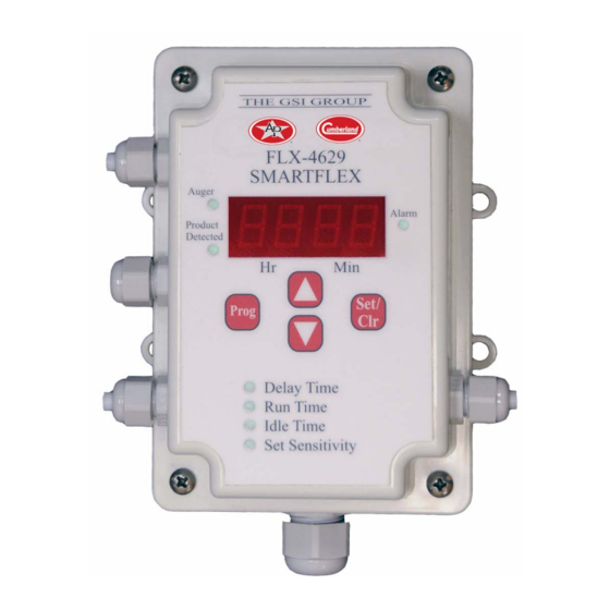
2. Smart-Flex (FLX-4629) Operation Instructions The Smart-Flex Controller The Smart-Flex controller has combined several feed system functions into one unit and is now able to communicate with the Network Master which enables remote monitoring and adjustment. The following instructions will help you to understand how to set and manage these functions correctly. All four (4) functions below can be programmed with the toggle switch in the OFF position or in the normal operating mode. -
Page 7: Setting The Maximum Run Time
2. Smart-Flex (FLX-4629) Operation Instructions Setting the Maximum Run Time The Maximum Run Time is defined as: The maximum time an auger is allowed to run during one feed cycle before shutting off and going into alarm mode. If this time is reached before the feed system is full, the auger will shut off and remain off until the Maximum Run Time is reset. -
Page 8: Setting The Maximum Idle Time
2. Smart-Flex (FLX-4629) Operation Instructions Setting the Maximum Idle Time The Maximum Idle Time is defined as: The time after feed is first detected until feed is no longer detected. Excessive Idle Time can be caused by animals not eating for long periods of time or by feed bridging in the drop tube in front of the sensor. -
Page 9: Setting The Sensitivity Level
2. Smart-Flex (FLX-4629) Operation Instructions Setting the Sensitivity Level The Smart-Flex has six (6) incremental levels of sensitivity adjustment settings to match the different situations and feed types you may encounter. Level 1 is the least sensitive and should only be used with very wet feed. -
Page 10: Setting The Unit I.d. Number (Only Used With Network Master)
2. Smart-Flex (FLX-4629) Operation Instructions Setting the Unit I.D. Number (Only Used with Network Master) When configuring the Smart-Flex to be used with a Network Master, each Smart-Flex must have a unique unit I.D. number in order to communicate properly. There is a maximum of twenty five (25) Smart-Flex controls that can be used with each Network Master. -
Page 11: Sensor Setting Guidelines
2. Smart-Flex (FLX-4629) Operation Instructions Sensor Setting Guidelines In addition to the six (6) sensitivity levels, there are two (2) situational levels: Level “Cd” refers to Chain Disk. Use this level when filling a Chain Disk feed system with a Flex-Flo auger that includes the Smart-Flex control. -
Page 12: Alarms
2. Smart-Flex (FLX-4629) Operation Instructions Alarms There are five (5) alarms modes for the Smart-Flex: Toggle switch turned off Display will flash “OFF” (See Figure 2G.) Pressure switch activated Display will flash “PrS” and sound an alarm (See Figure 2H.) Maximum Run Time exceeded Display will flash “run”... - Page 13 2. Smart-Flex (FLX-4629) Operation Instructions Figure 2I Figure 2J Figure 2K PNEG-1186 Smart-Flex (FLX-4629) Operation Instructions...
-
Page 14: Chapter 3 Wiring Diagrams
3. Wiring Diagrams Standard Configuration Figure 3A Standard Configuration PNEG-1186 Smart-Flex (FLX-4629) Operation Instructions... -
Page 15: Relay Box
3. Wiring Diagrams Relay Box Figure 3B Wiring Diagram for Relay Box PNEG-1186 Smart-Flex (FLX-4629) Operation Instructions... -
Page 16: Standard Mode
3. Wiring Diagrams Standard Mode The standard configuration of the Smart-Flex uses the proximity sensor (AP-2984). The two (2) wires from the proximity sensor connect to the terminals in the lid marked “Sensor +V” and “Sensor -V”. (See Figure 3C.) This configuration with the proximity sensor (AP-2984) is the only one that the set sensitivity levels 1 through 6 correspond to. -
Page 17: Extension Mode
3. Wiring Diagrams Extension Mode The Smart-Flex can be configured without the proximity sensor to control the Flex-Flo fill auger of an extension system. To use in extension mode without the proximity sensor, add a jumper wire connected to the terminals in the lid marked “Sensor +V” and “Ext. Mode”. (See Figure 3D.) In this configuration, the pressure switch will operate without setting off or sounding the alarm. -
Page 18: Chain Disk Mode
3. Wiring Diagrams Chain Disk Mode The Smart-Flex can be used as the Flex-Flo fill auger control to fill a chain disk feed system. For this configuration, the proximity sensor is not used. In place of the proximity sensor, connect a two (2) conductor cord from the terminals in the Smart-Flex lid marked “Sensor +V”... -
Page 19: Ir Plus Feed Sensor Or N.o. Micro Switch
3. Wiring Diagrams IR Plus Feed Sensor or N.O. Micro Switch The Smart-Flex can be connected to any N.O. Micro Switch or IR Plus Feed Sensor. For this configuration, the proximity sensor is not used. In place of the proximity sensor, connect a two (2) conductor cord from the terminals in the Smart-Flex lid marked “Sensor +V”... -
Page 20: Chapter 4 Smart-Flex Optional Equipment
4. Smart-Flex Optional Equipment Smart-Flex Extension Unit (FLX-4820) A Smart-Flex extension unit is available to extend the user interface to a more favorable location for easier access. The maximum distance the extension unit can be mounted away from the main Smart-Flex control is 200'. -
Page 21: Lid Clear Protector Cover Kit (Flx-4738)
4. Smart-Flex Optional Equipment Lid Clear Protector Cover Kit (FLX-4738) A clear protector cover kit is available to protect the Smart-Flex lid from damage to the mylar overlay by accidental contact with high pressure power washer spray. Install the kit according to the instructions that are supplied with it. -
Page 22: Chapter 5 Parts List
5. Parts List Smart-Flex Parts PNEG-1186 Smart-Flex (FLX-4629) Operation Instructions... - Page 23 5. Parts List Smart-Flex Parts List Ref # Part # Description E300-1008 Lid Fuse 250mA at 250V FLX-5183 Box Fuse 1A at 250V FLX-4802 Connector Cord FLX-4799 Top with Printed Circuit Board FLX-4799LB Smart-Flex I Top without Printed Circuit Board FLX-4799LB2 Smart-Flex II Top without Printed Circuit Board FLX-4801...
-
Page 24: Smart-Flex Relay Box Assembly (Flx-4778)
5. Parts List Smart-Flex Relay Box Assembly (FLX-4778) PNEG-1186 Smart-Flex (FLX-4629) Operation Instructions... - Page 25 5. Parts List Smart-Flex Relay Box Assembly (FLX-4778) Parts List Ref # Part # Description FLX-4559 4 x 6 Electrical Box (Bottom) FLX-4569 Back Plate, 4 x 6 Control Box Flex-Flo System FLX-4620 Relay Bracket f/ FLX-4619 S-8186 Screw, SMSB #6 x 1/4" PHP ZN FLX-4619 Relay, 4 Pole, ST, N.O., 240V S-8823...
-
Page 26: Ap 4 X 6 Electrical Box Clear Cover Kit (Ap-4738)
5. Parts List AP 4 x 6 Electrical Box Clear Cover Kit (AP-4738) PNEG-1186 Smart-Flex (FLX-4629) Operation Instructions... - Page 27 5. Parts List AP 4 x 6 Electrical Box Clear Cover Kit (AP-4738) Parts List Ref # Part # Description AP-4700 Cover, Clear, 4 x 6 PVC BOX, 1/4 Lexan AP-4709 Spacer, Round Through Hole, Nylon, Black, 0.195" I.D. x 3/8" O.D. x 1-1/2" S-10106 Flat Washer #10, 11/16"...
- Page 28 NOTES PNEG-1186 Smart-Flex (FLX-4629) Operation Instructions...
-
Page 29: Chapter 6 Warranty
0 to 3 years - no cost to end-user All Fiberglass Propellers Lifetime 3 to 5 years - end-user pays 25% AP and Cumberland Flex-Flo/Pan Feeding System Motors 2 Years 5 to 7 years - end-user pays 50% 7 to 10 years - end-user pays 75%... - Page 30 1004 E. Illinois St. Assumption, IL 62510-0020 Phone: 1-217-226-4421 Fax: 1-217-226-4420 www.gsiag.com AP and Cumberland are a part of GSI, a worldwide brand of AGCO Corporation. Copyright © 2015 by The GSI Group, LLC Printed in the USA CN-315800...
Need help?
Do you have a question about the Smart-Flex FLX-4629 and is the answer not in the manual?
Questions and answers
My flx 4629 says off but the toggle switch is in on position. Press the set clr button and says 340 for delay. Will not run feed or reset when flip the on/off switch.
If the Cumberland Smart-Flex FLX-4629 is not running feed despite the toggle switch being in the on position, possible issues include:
1. Maximum Run Time exceeded – If the auger has run for the maximum allowed time without filling the system, it will shut off and trigger an alarm. The display will flash “run.”
2. Maximum Idle Time exceeded – If the system has been idle too long, it will enter alarm mode. The display will flash “IdL.”
3. Pressure switch activated – This triggers an alarm and stops operation. The display will flash “PrS.”
4. Lost communication with the Network Master – This causes the system to stop. The display will flash “AC14.”
To resume operation after any of these alarms (except toggle switch off), press the Set/Clr button to reset the alarm.
This answer is automatically generated
the set/clr will not reset the alarms.
ON th ePLX 4629 smartflex, what does it mean when the red alarm is displayed
The red Alarm LED on the Cumberland FLX-4629 Smart-Flex indicates that the displayed auger Run Time has reached the Maximum Run Time setting. When this happens, the auger shuts off, the green Auger LED turns off, and the control enters alarm mode while flashing "Run" on the display.
This answer is automatically generated
On the FLX 4629 smartflex, What does it mean when the alarm light is displaying red.
A red alarm light on the Cumberland FLX-4629 Smart-Flex indicates that one of the five alarm conditions has occurred:
1. Toggle switch turned off – display flashes “OFF”.
2. Pressure switch activated – display flashes “PrS” and sounds an alarm.
3. Maximum Run Time exceeded – display flashes “run” and sounds an alarm.
4. Maximum Idle Time exceeded – display flashes “IdL” and sounds an alarm.
5. Lost communication with Network Master – display flashes “AC14”.
To reset alarms 2 through 5, the Set/Clr button must be pushed.
This answer is automatically generated
Code ACO5 mean