Table of Contents
Advertisement
Quick Links
Advertisement
Table of Contents

Related Manuals for Fibocom L850-GL


Summary of Contents for Fibocom L850-GL
- Page 1 L850-GL Hardware User Manual Version:V1.0.3 Update date:2/25/2017...
- Page 2 Applicability Table Product model Description L850-GL Reproduction forbidden without Fibocom Wireless Inc. written authorization - All Rights Reserved. L850-GL Hardware User Manual Page 2 of 51...
- Page 3 V1.0.2 2017-02-09 Update the content of PCIe Add the power Consumption of 3CA V1.0.3 2017-02-25 Add product certification of warnings Reproduction forbidden without Fibocom Wireless Inc. written authorization - All Rights Reserved. L850-GL Hardware User Manual Page 3 of 51...
-
Page 4: Table Of Contents
3.4 USB Interface............................. 28 3.4.1 USB Interface Definition......................... 28 3.4.2 USB2.0 Interface Application......................28 3.5 PCIe Interface............................ 29 3.5.1 PCIe Interface Definition........................ 29 Reproduction forbidden without Fibocom Wireless Inc. written authorization - All Rights Reserved. L850-GL Hardware User Manual Page 4 of 51... - Page 5 4.6 Antenna Design..........................45 5 Structure Specification......................47 5.1 Product Appearance..........................47 5.2 Dimension of Structure........................47 5.3 M.2 Interface Model...........................48 5.4 M.2 Connector............................48 Reproduction forbidden without Fibocom Wireless Inc. written authorization - All Rights Reserved. L850-GL Hardware User Manual Page 5 of 51...
- Page 6 5.5 Storage..............................49 5.5.1 Storage Life............................49 5.6 Packing..............................49 5.6.1 Tray Package........................... 50 5.6.2 Tray size............................51 Reproduction forbidden without Fibocom Wireless Inc. written authorization - All Rights Reserved. L850-GL Hardware User Manual Page 6 of 51...
-
Page 7: Foreword
The document describes the electrical characteristics, RF performance, dimensions and application environment, etc. of L850-GL (hereinafter referred to as L850). With the assistance of the document and other instructions, the developers can quickly understand the hardware functions of L850 modules and develop products. -
Page 8: Overview
Dimension : 30 x 42 x 2.3mm characteristics Weight: About5.8 g Interface WWAN Main Antenna x 1 Antenna WWAN Diversity Antenna x 1 Reproduction forbidden without Fibocom Wireless Inc. written authorization - All Rights Reserved. L850-GL Hardware User Manual Page 8 of 51... -
Page 9: Warnings
(1) This device may not cause harmful interference, and (2) this device must accept any interference received, including interference that may cause undesired operation. Reproduction forbidden without Fibocom Wireless Inc. written authorization - All Rights Reserved. L850-GL Hardware User Manual... - Page 10 As long as 2 conditions above are met, further transmitter test will not be required. However, the OEM integrator is still responsible for testing their end-product for any additional compliance requirements required with this module installed Reproduction forbidden without Fibocom Wireless Inc. written authorization - All Rights Reserved. L850-GL Hardware User Manual Page 10 of 51...
-
Page 11: Ic Statement
Cet appareil est conforme à la norme RSS-310 d'Industrie Canada. L'opération est soumise à la condition que cet appareil ne provoque aucune interférence nuisible. Reproduction forbidden without Fibocom Wireless Inc. written authorization - All Rights Reserved. L850-GL Hardware User Manual Page 11 of 51... -
Page 12: Ce Statement
2.3.3 CE Statement ► EU Regulatory Conformance Hereby, We, declares that the radio equipment type L850-GL is in compliance with Fibocom Wireless Inc. the Directive 2014/53/EU. In all cases assessment of the final product must be mass against the Essential requirements of the Directive 2014/53/EU Articles 3.1(a) and (b), safety and EMC respectively, as well as any relevant Article... -
Page 13: Ca Combinations
4+5+30, 4+12+30, 4+29+30 5+66+2, 13+66+2 2+2+5, 2+2+13 3+3+7, 3+7+7, 3+3+20 2 contiguous plus inter-band 4+4+5, 4+4+13 5+66+66, 13+66+66, 66+66+2, 66+66+66 Reproduction forbidden without Fibocom Wireless Inc. written authorization - All Rights Reserved. L850-GL Hardware User Manual Page 13 of 51... -
Page 14: Application Framework
2.5 Application Framework The peripheralapplicationsfor L850 module are shown in Figure 2-1: Figure2-1 Application Framework Reproduction forbidden without Fibocom Wireless Inc. written authorization - All Rights Reserved. L850-GL Hardware User Manual Page 14 of 51... -
Page 15: Hardware Framework
Figure 2-2 Hardware Framework 3 Application Interface 3.1 M.2Interface The L850 module applies standard M.2 Key-B interface, with a total of 75 pins. Reproduction forbidden without Fibocom Wireless Inc. written authorization - All Rights Reserved. L850-GL Hardware User Manual Page 15 of 51... -
Page 16: Pin Distribution
3.1.1 Pin Distribution Figure 3-1 Pin Distribution Note: Pin “Notch” represents the gap of the gold fingers. Reproduction forbidden without Fibocom Wireless Inc. written authorization - All Rights Reserved. L850-GL Hardware User Manual Page 16 of 51... -
Page 17: Pin Definition
GND,L850 M.2 module is configured as CONFIG_0 the WWAN – PCIe,USB3.0 interface type I2S_RX I2S Serial receive data, CMOS 1.8V Reproduction forbidden without Fibocom Wireless Inc. written authorization - All Rights Reserved. L850-GL Hardware User Manual Page 17 of 51... - Page 18 PCIe TX Differential signals PETn0 Negative I2C Serial data input/output, GNSS_SDA CMOS 1.8V Reserved PETp0 PCIe TX Differential signals Positive Reproduction forbidden without Fibocom Wireless Inc. written authorization - All Rights Reserved. L850-GL Hardware User Manual Page 18 of 51...
- Page 19 WiFi/BT modules. IDC_UART_TXD, 3.3/1.8V Reserved ANTCTL1 Tunable ANT CTRL1 CMOS 1.8V Wireless Coexistence between WWAN COEX2 CMOS 1.8V and WiFi/BT modules, IDC_UART_RXD Reproduction forbidden without Fibocom Wireless Inc. written authorization - All Rights Reserved. L850-GL Hardware User Manual Page 19 of 51...
- Page 20 PD:Pull-Down PU:Pull-Up T:Tristate OD:Open Drain PP:Push-Pull PI: Power Input PO: Power Output Note: The unused pins can be left floating. Reproduction forbidden without Fibocom Wireless Inc. written authorization - All Rights Reserved. L850-GL Hardware User Manual Page 20 of 51...
-
Page 21: Power Supply
The capacitor for battery power supply can be reduced to 100~200uF Filter out the interference generated from the clock 1uF,100nF Digital signal noise and digital signals Reproduction forbidden without Fibocom Wireless Inc. written authorization - All Rights Reserved. L850-GL Hardware User Manual Page 21 of 51... -
Page 22: Logic Level
The L850module 3.3V logic level definition as shown in the following table: Parameters Minimum Typical Maximum Unit 3.3V logic level 3.135 3.465 3.465 -0.3 Reproduction forbidden without Fibocom Wireless Inc. written authorization - All Rights Reserved. L850-GL Hardware User Manual Page 22 of 51... -
Page 23: Power Consumption
LTE FDD Data transfer Band 18 @+23dBm LTE FDD Data transfer Band 19 @+23dBm LTE FDD Data transfer Band 20 @+23dBm Reproduction forbidden without Fibocom Wireless Inc. written authorization - All Rights Reserved. L850-GL Hardware User Manual Page 23 of 51... - Page 24 Band 30 @+22dBm 1330 Band 66 @+22dBm Note: The data above is an average value obtained by testing some samples. Reproduction forbidden without Fibocom Wireless Inc. written authorization - All Rights Reserved. L850-GL Hardware User Manual Page 24 of 51...
-
Page 25: Control Signal
20ms (100msis recommended). Meanwhile, the module will output 1.8V voltage through VSD2_1V8 pin and start the initialization process. The start-up timing is shown in Figure 3-5: Reproduction forbidden without Fibocom Wireless Inc. written authorization - All Rights Reserved. L850-GL Hardware User Manual... -
Page 26: Module Shutdown
SIM card and some other parameters from memory, then clear the memory and PMU will be powered off. After shutdown, the VSD2_1V8 voltage is also shut down. The software control timing isshown in Figure 3-6: Reproduction forbidden without Fibocom Wireless Inc. written authorization - All Rights Reserved. L850-GL Hardware User Manual Page 26 of 51... -
Page 27: Module Reset
Figure 3-7: Figure 3-7 Recommended Design for Reset Circuit The reset control timing is shown in Figure 3-8: Reproduction forbidden without Fibocom Wireless Inc. written authorization - All Rights Reserved. L850-GL Hardware User Manual Page 27 of 51... -
Page 28: Usb Interface
USB interface is used for debugging only, so it only needs to introduce the USB interface test in hardware design. Reproduction forbidden without Fibocom Wireless Inc. written authorization - All Rights Reserved. L850-GL Hardware User Manual Page 28 of 51... -
Page 29: Pcie Interface
PCIe PME Wake. Open Drain with pull up on PEWAKE# CMOS 3.3V platform,active low 3.5.2 PCIe Interface Application The reference circuit is shown in Figure 3-9: Reproduction forbidden without Fibocom Wireless Inc. written authorization - All Rights Reserved. L850-GL Hardware User Manual Page 29 of 51... - Page 30 2 times the spacing of normal differential lines (S1<2S); Reproduction forbidden without Fibocom Wireless Inc. written authorization - All Rights Reserved. L850-GL Hardware User Manual...
-
Page 31: Usiminterface
The USIM pins descriptionas shown in the following table: Pin Name I/O Reset Value Description Type UIM_PWR USIM power supply 1.8V/3V Reproduction forbidden without Fibocom Wireless Inc. written authorization - All Rights Reserved. L850-GL Hardware User Manual Page 31 of 51... -
Page 32: Usim Interface Circuit
3.6.2.2 N.O. SIM Card Slot The reference circuit design for N.O. (Normally Open) SIM card slot is shown in Figure 3-13: Reproduction forbidden without Fibocom Wireless Inc. written authorization - All Rights Reserved. L850-GL Hardware User Manual Page 32 of 51... -
Page 33: Usim Hot-Plugging
After the SIM card hot-plugging detection functionis enabled, the module detects that the SIM card is insertedwhen the SIM_DETECT pin is high, then executes the initialization program and finish the Reproduction forbidden without Fibocom Wireless Inc. written authorization - All Rights Reserved. L850-GL Hardware User Manual... -
Page 34: Usim Design
System status LED, drain output. WOWWAN# CMOS 1.8V Module wakes upHost (AP). PA Blanking output, externalGPS control TX_BLANKING CMOS 1.8V signal. Reproduction forbidden without Fibocom Wireless Inc. written authorization - All Rights Reserved. L850-GL Hardware User Manual Page 34 of 51... -
Page 35: Led#1Signal
Pull low 1s then pull high (pulse signal). Idle/Sleep High level The WOWWAN# timing is shown in Figure 3-15: Figure 3-15 WOWWAN#Timing Reproduction forbidden without Fibocom Wireless Inc. written authorization - All Rights Reserved. L850-GL Hardware User Manual Page 35 of 51... -
Page 36: Tx_Blanking
Function High/Floating WWAN function is enabled, the module exits the Flight mode. WWAN function is disabled, the module entersFlight mode. Reproduction forbidden without Fibocom Wireless Inc. written authorization - All Rights Reserved. L850-GL Hardware User Manual Page 36 of 51... -
Page 37: Bodysar
RFFE2 clock,Open Drain output RFE_RFFE2_ CMOS Tunable ANT control,MIPI Interface, SDATA 3.3/1.8V RFFE2 data,Open Drain output ANTCTL0 CMOS 1.8V Tunable ANT control,GPO interface, Reproduction forbidden without Fibocom Wireless Inc. written authorization - All Rights Reserved. L850-GL Hardware User Manual Page 37 of 51... -
Page 38: Config Interface
Please refer to ”PCI Express M.2 Specification Rev1.0” for more details. 3.12Other Interfaces The module does not support other interfaces yet. Reproduction forbidden without Fibocom Wireless Inc. written authorization - All Rights Reserved. L850-GL Hardware User Manual Page 38 of 51... -
Page 39: Radio Frequency
The L850 module adopts standard M.2 module RF connectors, the model name is from ECT 818004607 company, and the connector size is 2*2*0.6m. The connector dimension is shown as following picture: Reproduction forbidden without Fibocom Wireless Inc. written authorization - All Rights Reserved. L850-GL Hardware User Manual Page 39 of 51... - Page 40 Figure 4-2 RF connector dimensions Figure 4-3 0.81mm coaxial antenna dimensions Figure 4-4 Schematic diagram of 0.81mm coaxial antenna connected to the RF connector Reproduction forbidden without Fibocom Wireless Inc. written authorization - All Rights Reserved. L850-GL Hardware User Manual Page 40 of 51...
-
Page 41: Operating Band
2110 - 2200 Band 38 IMT-E 2600MHz LTE TDD 2570 - 2620 Band 39 TDD 1900MHZ LTE TDD 1880 - 1920 Reproduction forbidden without Fibocom Wireless Inc. written authorization - All Rights Reserved. L850-GL Hardware User Manual Page 41 of 51... -
Page 42: Transmitting Power
Band 18 23±1 10MHz Bandwidth, 1 RB Band 19 23±1 10MHz Bandwidth, 1 RB Band 20 23±1 10MHz Bandwidth, 1 RB Reproduction forbidden without Fibocom Wireless Inc. written authorization - All Rights Reserved. L850-GL Hardware User Manual Page 42 of 51... -
Page 43: Receiver Sensitivity
Band 8 10MHz Bandwidth Band 11 10MHz Bandwidth Band 12 10MHz Bandwidth Band 13 10MHz Bandwidth Band 17 10MHz Bandwidth Reproduction forbidden without Fibocom Wireless Inc. written authorization - All Rights Reserved. L850-GL Hardware User Manual Page 43 of 51... -
Page 44: Gnss
Description Condition Test Result GPS fixing GPS tracking GLONASS fixing Power GLONASS tracking BeiDou fixing BeiDou tracking Sleep Reproduction forbidden without Fibocom Wireless Inc. written authorization - All Rights Reserved. L850-GL Hardware User Manual Page 44 of 51... -
Page 45: Antenna Design
LTE Band 8(900): 80 MHz LTE Band 11(1500): 68 MHz LTE Band 12(700): 47 MHz LTE Band 13(700): 41 MHz Reproduction forbidden without Fibocom Wireless Inc. written authorization - All Rights Reserved. L850-GL Hardware User Manual Page 45 of 51... - Page 46 GLONASS: 8MHz BeiDou: 4MHz Impedance 50Ohm Input power > 26dBmaverage power WCDMA & LTE Recommended standing-wave ≤ 2:1 ratio (SWR) Reproduction forbidden without Fibocom Wireless Inc. written authorization - All Rights Reserved. L850-GL Hardware User Manual Page 46 of 51...
-
Page 47: Structure Specification
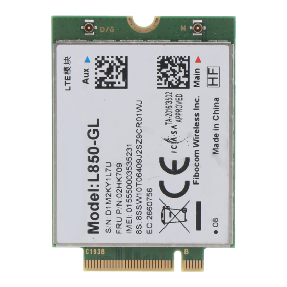
Figure 5-1 Module Appearance 5.2 Dimension of Structure The structuraldimensionof the L850 module is shown in Figure 5-2: Figure 5-2 Dimension of Structure Reproduction forbidden without Fibocom Wireless Inc. written authorization - All Rights Reserved. L850-GL Hardware User Manual Page 47 of 51... -
Page 48: Interface Model
LOTES company with the model APCI0026-P001A as shown in Figure 5-3. The package of connector, please refer to the specification. Reproduction forbidden without Fibocom Wireless Inc. written authorization - All Rights Reserved. L850-GL Hardware User Manual Page 48 of 51... -
Page 49: Storage
The module is a precision electronic product, and may suffer permanent damage if no correct electrostatic protection measures are taken. Reproduction forbidden without Fibocom Wireless Inc. written authorization - All Rights Reserved. L850-GL Hardware User Manual Page 49 of 51... -
Page 50: Tray Package
The L850 module uses tray package,20 pcs are packed in each tray, with 5 trays in each box and 6 boxes in each case. Tray packaging process is shown in Figure 5-4: Figure 5-4 Tray Packaging Process Reproduction forbidden without Fibocom Wireless Inc. written authorization - All Rights Reserved. L850-GL Hardware User Manual Page 50 of 51... -
Page 51: Tray Size
175.0±0.5 6.0±0.3 0.5±0.1 43±0.3 33.0±0.3 ITEM 294.0±0.3 159.0±0.3 20.0±0.5 9.0±0.5 24.5±0.5 187.5±0.2 ITEM 105.0±0.2 9.0±0.2 Figure 5-5Tray Size (Unit: mm) Reproduction forbidden without Fibocom Wireless Inc. written authorization - All Rights Reserved. L850-GL Hardware User Manual Page 51 of 51...
Need help?
Do you have a question about the L850-GL and is the answer not in the manual?
Questions and answers