
Subscribe to Our Youtube Channel
Related Manuals for Clarke WOODWORKER CCS12B


Summary of Contents for Clarke WOODWORKER CCS12B
- Page 1 12”( ) CONTRACTOR TABLE SAW MODEL NO: CCS12B PART NO: 6460015 OPERATION & MAINTENANCE INSTRUCTIONS ORIGINAL INSTRUCTIONS GC02-22...
-
Page 2: Specifications
INTRODUCTION Thank you for purchasing this CLARKE product. This table saw has been designed to perform the sawing operation of ripping, cross-cutting, bevelling and mitering wood and wood products. This unit is designed for use with an 12” (315mm) carbide tipped blade. -
Page 3: Environmental Recycling Policy
GUARANTEE This product is guaranteed against faulty manufacture for a period of 12 months from the date of purchase. Please keep your receipt which will be required as proof of purchase. This guarantee is invalid if the product is found to have been abused or tampered with in any way, or not used for the purpose for which it was intended. -
Page 4: Safety Symbols
SAFETY SYMBOLS Read instruction Wear dust mask manual before use Wear safety glasses Wear ear defenders Indoor Use Only The above safety symbols appear on the product. SAFETY WARNINGS CAUTION: DO NOT LET FAMILIARITY WITH YOUR TABLE SAW MAKE YOU CARELESS. - Page 5 • Work in a well-ventilated area. • Work with approved safety equipment, such as dust masks, that are specially designed to filter microscopic particles. • If possible use/connect to a suitable dust extractor. • Noise can be a health hazard. The permitted noise level is exceeded when working.
- Page 6 16. Guard against electric shock and avoid body contact with earthed or grounded surfaces. 17. Before use, inspect the extension cable and replace if damaged. This product is recommended for indoor use only. 18. Avoid unintentional starting. Make sure the switch is in the OFF position before connecting the machine to the power supply.
-
Page 7: Additional Safety Rules For Table Saws
32. Keep blades sharp and clean for better and safer performance. Inspect power cables periodically and if damaged have them repaired. 33. Repairs should only be carried out by qualified persons using original spare parts, otherwise this may result in considerable danger to the user. 34. -
Page 8: Saw Blades
19. Provide adequate support to the rear and the sides of the saw table for long or wide workpieces. 20. NEVER leave the saw running unattended. Turn the power off and do not leave the saw until it comes to a complete stop. 21. -
Page 9: Remaining Hazards
7. Make sure the blade is not contacting the riving knife or workpiece before the switch is turned on. 8. Wear gloves when handling saw blades and rough material. Saw blades shall be carried in a holder whenever practicable. Only wear gloves when the saw is switched off and unplugged. -
Page 10: Electrical Connections
ELECTRICAL CONNECTIONS WARNING! READ THESE ELECTRICAL SAFETY INSTRUCTIONS THOROUGHLY BEFORE CONNECTING THE PRODUCT TO THE MAINS SUPPLY. Before switching the product on, make sure that the voltage of your electricity supply is the same as that indicated on the rating plate. This product is designed to operate on 230VAC 50Hz. -
Page 11: Machine Overview
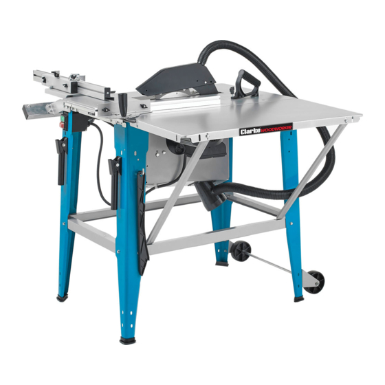
MACHINE OVERVIEW Mitre fence assembly Lifting handles Dust extract duct Blade height adjuster Blade Guard On/Off switch Parallel Fence assembly Transport wheels Table extension Push stick Blade angle adjuster Blade removal wrenches Blade height display scale Parts & Service: 020 8988 7400 / E-mail: Parts@clarkeinternational.com or Service@clarkeinternational.com... -
Page 12: Tools Required
INVENTORY The following items should be supplied in the carton. If any parts are missing, do not attempt to use your table saw until the missing parts are obtained. Machine assembly Slide rail Work table extension 17a Brackets for slide rail (2) Rear table support stays (2) Sliding mitre table assembly Side table support stays (2) -
Page 13: Stand Assembly
ASSEMBLY STAND ASSEMBLY 1. Ensure the blade is retracted inside the machine by turning the height adjuster. Turn the machine upside down, ideally on a soft surface. 2. Fix the dust extract duct connector to the motor housing with 4 x bolts using a 7mm flat or ring spanner. - Page 14 6. Loosen the bolts on the corner diagonally opposite the switch and bolt the hose securing bracket to the table (shown the right way up). 7. With the help of an assistant, turn the assembly the right way up. 8. With the assembly standing on a flat, level floor, check that the assembly is standing level and that the legs are an equal distance apart before tightening the securing...
-
Page 15: Extension Table
EXTENSION TABLE The extension table can be fitted to either the side or end of the main work table, as required. Use either the long or short support arms to support the extension table in your chosen location. 1. Connect either the rear or side table support arms using the bolts, washers and nuts supplied. -
Page 16: Floor Mounting
3. A 4” duct will be required with the dust extractor to connect to the adaptor on the bottom of the machine. WARNING: EXCESSIVE SAWDUST BUILD UP AROUND THE MOTOR COULD POSSIBLY IGNITE AND CAUSE DAMAGE TO THE MOTOR, TABLE SAW OR YOUR WORKSHOP. - Page 17 1. Take the sliding plate, complete with track slide and angle pointer fitted, and add the handle using a 20mm coach bolt. 1. Attach the rip fence carrier track to the table front using 2 x carriage bolts M6x25, 2 washers and 2 locking levers.
-
Page 18: Sliding Table Assembly
SLIDING TABLE ASSEMBLY The sliding table comprises the following components: 1. Guide Rail 2. Sliding Table assembly 3. Support bracket (x2) 4. Mitre fence 5. Folding Stop Block 6. Fixing Pack 1. Remove the bolts at the top of the leg and use these to bolt the support brackets, to the left side of the table. -
Page 19: Accessory Storage
5. Next, add the locking handle using a flat washer above and below the support and securing from below with the 12mm nut supplied. 6. Check that the fence support hinges freely and that pressing down on the handle will lock the support in position. 7. -
Page 20: Operation
OPERATION CAUTION: BEFORE STARTING UP THE SAW ALWAYS CHECK THE FOLLOWING POINTS: 1. Is the saw blade firmly tightened and can the blade rotate freely? 2. Are all the locking levers firmly locked? 3. Is the riving knife aligned with the saw blade? 4. - Page 21 ADJUSTMENTS SETTING THE BLADE HEIGHT 1. Set the blade height as required by using the adjustment handle under the work table. • The height scale shows the height above the table top. SETTING THE BLADE ANGLE 1. Release the bevel locking knobs on either end of the machine.
-
Page 22: Cutting Narrow Workpieces
CUTTING PRACTICE After every new adjustment, we recommend you to make a trial cut in order to check the new settings. RIPPING CUTS & CROSS CUTS Ripping is when you use the saw to cut along the grain of the wood. The parallel fence must always be used when making ripping cuts. -
Page 23: Mitre Cuts
When not in use, store the push stick in its holder on the side of the saw. Replace a lost damaged push stick immediately. MITRE CUTS 1. Adjust the fence to the required angle against the mitre gauge and lock in place with the cam lever. -
Page 24: Maintenance
MAINTENANCE WARNING: REMOVE THE PLUG FROM THE MAINS POWER SUPPLY BEFORE CARRYING OUT ANY ADJUSTMENT OR MAINTENANCE. Your saw has been designed to operate over a long period of time with a minimum of maintenance. Continuous satisfactory operation depends upon proper tool care and regular cleaning. - Page 25 NOTE: Replacement blades manufactured to EN847-1 standards are available from your CLARKE dealer, part No 649220. Parts & Service: 020 8988 7400 / E-mail: Parts@clarkeinternational.com or Service@clarkeinternational.com...
-
Page 26: Troubleshooting
TROUBLE SHOOTING Problem Probable cause Solution Saw will not start 1. Saw not plugged in 1. Plug in the machine 2. Fuse blown 2. Replace fuse 3. Power cable damaged 3. Have cable replaced by your dealer. Does not make accurate 1. -
Page 27: Parts List
PARTS LIST No Item No Item No Item Rubber foot cap End plate Blade wrench Leg with aperture Tilting knob Duct hose Lifting handle Axle bracket LH Nut M6 Mounting bracket Wheel Flat washer Locking bracket Short crossbeam Spring washer Axle Bolt M6 x 16 Track... - Page 28 140 Side table support 107 Hex bolt M10x20 124 Bolt M10x65 USEFUL ITEMS FROM THE CLARKE CATALOGUE Refer to the Clarke website www.clarkeinternational.com for a full range of items for use with this saw. See also the following accessories; CARS1 Roller Stand...
-
Page 29: Parts Diagram
PARTS DIAGRAM Parts & Service: 020 8988 7400 / E-mail: Parts@clarkeinternational.com or Service@clarkeinternational.com... - Page 30 DECLARATION OF CONFORMITY-UK Parts & Service: 020 8988 7400 / E-mail: Parts@clarkeinternational.com or Service@clarkeinternational.com...
-
Page 31: Declaration Of Conformity-Eu
DECLARATION OF CONFORMITY-EU Parts & Service: 020 8988 7400 / E-mail: Parts@clarkeinternational.com or Service@clarkeinternational.com...
Need help?
Do you have a question about the WOODWORKER CCS12B and is the answer not in the manual?
Questions and answers