
Subscribe to Our Youtube Channel
Related Manuals for Clarke CCS12


Summary of Contents for Clarke CCS12
- Page 1 12in (305mm) 12in (305mm) CONTRACTOR’S SAW CONTRACTOR’S SAW Model No. CCS12 0410 Part No. 6460000 OPERATING & MAINTENANCE INSTRUCTIONS Serial/Batch No: ........
- Page 2 Considerable noise is generated by this type of equipment. Ear protection should be used at all times PARTS & SERVICE CONTACTS For Spare Parts and Service, please contact your nearest dealer, or CLARKE International, on one of the following numbers. PARTS & SERVICE TEL: 020 8988 7400 PARTS &...
-
Page 3: Table Of Contents
Thank you for purchasing this CLARKE 305mm (12") Contractors Saw which is designed for INDOOR USE ONLY Before operating the machine, please read this leaflet thoroughly and follow the instructions carefully. In doing so you will ensure the safety of yourself and that of others around you, and you can look forward to it giving you long and satisfactory service. -
Page 4: General Safety Precautions
GENERAL SAFETY RULES FOR OPERATING MACHINERY WARNING: As with all machinery, there are certain hazards involved with their operation and use. Exercising respect and caution will considerably lessen the risk of personal injury. However, if normal safety precautions are overlooked or ignored, personal injury to the operator or damage to property, may result. - Page 5 • • MAINTAIN MACHINE IN TOP ALWAYS ensure that ADEQUATE LIGHTING is CONDITION. available. A minimum intensity of 300 lux Keep tools sharp should be provided. Ensure that lighting is and clean for the placed so that you will not be working in your best and safest own shadow.
-
Page 6: Additional Precautions For Table Saws
DO NOT operate the machine with the guards removed. They must all be in place and securely fastened when performing any operation. Use ONLY approved replacement saw blades. Contact your local CLARKE dealer for advice. The use of inferior blades may increase the risk of injury. -
Page 7: Features
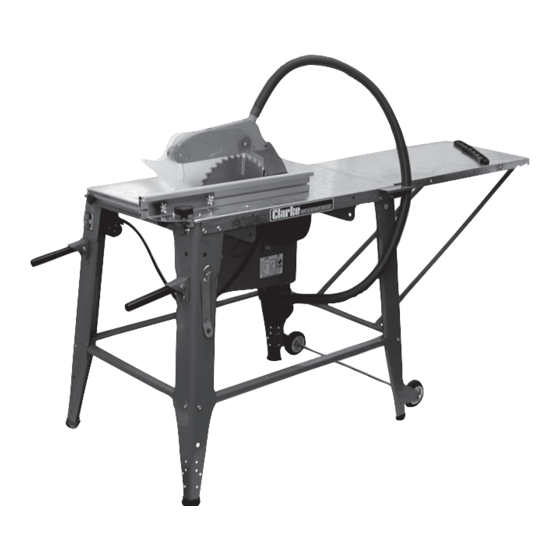
FEATURES The Contractors Saw may be used for rip cutting or cross cutting timber up to 90mm (3½”) in depth. The Table extension provides support for extra long pieces. A double height Rip Fence is provided and may be secured at any desired position for quick and accurate rip sawing. -
Page 8: Unpacking & Parts Identification
Unpack the shipping carton, and lay out the components so that they can be clearly identified. Should there be any deficiencies, or damage suffered in transit, you should immediately contact your CLARKE dealer. LOOSE PARTS Wheel and Axle Assy (1) -
Page 9: Principal Parts Diagram
PRINCIPAL PARTS Fig.1 NOTE: The letters in brackets refer to the identification letters given in the illustrations on page 8 1 - Saw Blade 12 - Motor 2 - Riving Knife (G) 13 - Lower Blade Guard Box 3 - Upper Blade Guard (C) 14 - Table Extension (AA) 4 - Rip Fence (B) 15 - Table Extension Brace (Y) -
Page 10: Assembly
ASSEMBLY Unless otherwise specified, DO NOT fully tighten the fixing nuts during assembly. Due to the sharp edges associated with some of thge components, it is advised that gloves be worn during the assembly process. A. Legs and Braces Fig.2 1. - Page 11 D. Table Extension Fig.5 Lay the table extension face down and adjoining the table top in the manner shown in Fig. 5. Remove the two screws previously entered to secure the leg to the table top, then bolt the table extension to the table top using the same nuts, washers and screws, and a third screw for the third mounting as shown.
- Page 12 Fig.8 ✗ ✔ ✗ IMPORTANT! The Riving Knife MUST be completely in-line with the saw blade. Should it not be so, having followed these assembly instructions, adjustments are necessary, which are described on page 19. IMPORTANT: The Riving Kife must ALWAYS be in place and in good condition G.Upper Blade Guard &...
- Page 13 H. Rip Fence Guide Fig.11 16. Fit the Rip Fence Guide to the front end of the table using the screws, rubber washers, flat washers and nuts provided in the manner shown in Fig.11. Tighten the nuts firmly in order to squeeze the rubber washer tightly..but do not over tighten.
- Page 14 J. Rip Fence NOTE: The Rip Fence may be used in either high or low position. Fig14 illustrates the fence assembled in the high position with the work bearing against face ‘A’. Fig.14 Assembly is as follows: 19. Slide the large screws (C) into the channel in the rip fence as indicated, then mount...
-
Page 15: Electrical Connections
ELECTRICAL CONNECTIONS This appliance is fitted with a standard, 230 Volt (50Hz) BS 1363 approved 13 amp plug, for connection to a standard domestic 13 Amp electrical supply. We strongly recommend that connection be via a Residual Current Device (RCD). WARNING! THIS APPLIANCE MUST BE EARTHED IMPORTANT: Should the plug be replaced, it is important to note that he wires in the mains lead are coloured in accordance with the following code... -
Page 16: Adjustments
ADJUSTMENTS Before carrying out any adjustments, ensure the machine is disconnected from the electrical supply For normal ripping or cross cutting, The blade should be exactly perpendicular to the table. To check and adjust, you should proceed as follows: Raise the blade to its maximum height by using the handle mounted on the front of the Lower Blade Guard box, shown in Fig. -
Page 17: Operation
It must be allowed to move laterally. • Longer workpieces should be adequately supported. Roller Supports, ideal for this purpose, are available from your Clarke dealer When switching OFF, by pushing the red stop button marked ‘O’, the blade should stop within 8- 10 seconds. -
Page 18: Bevel Cutting
Long pieces of work must be supported at table height, and the workpiece must be free to move easily. It is advised to use an assistant for very long pieces. Roller Supports, ideal for this purpose, are available from your Clarke dealer 3. BEVEL CUTTING Set the blade angle using a suitable template, by slackening off the two lower blade guard securing knobs (see Fig. - Page 19 B. Blade Replacement 1. Slacken the clamping, bolt securing the riving knife, and move the knife sufficiently for the new blade to be installed. 2. Taking great care to avoid damaging your hands on the sharp teeth, slide the blade through the blade slot and on to the shoulder of the inner flange, ensuring it is the correct way round.
-
Page 20: Parts List
PARTS LIST No. Description Part No. Description Part No. Lower blade Guard Box TMCCS1201 Blade Angle cale TMCCS1244 Motor Guidance PLate TMCCS1202 Blade Height Scale TMCCS1245 Plate Lever TMCCS1203 Coach Bolt TMCCS1247 Guidance Frame TMCCS1204 C’sk Screw TMCCS1248 Crank Complete TMCCS1205 Flat Washer TMCCS1249... -
Page 21: Part Diagram
PARTS DIAGRAM... -
Page 22: Specifications
Part Number ................6460000 Please note that the details and specifications contained herein, are correct at the time of going to print. However, CLARKE International reserve the right to change specifications at any time without prior notice. Always consult the machine’s data plate ACCESSORIES 1.
Need help?
Do you have a question about the CCS12 and is the answer not in the manual?
Questions and answers