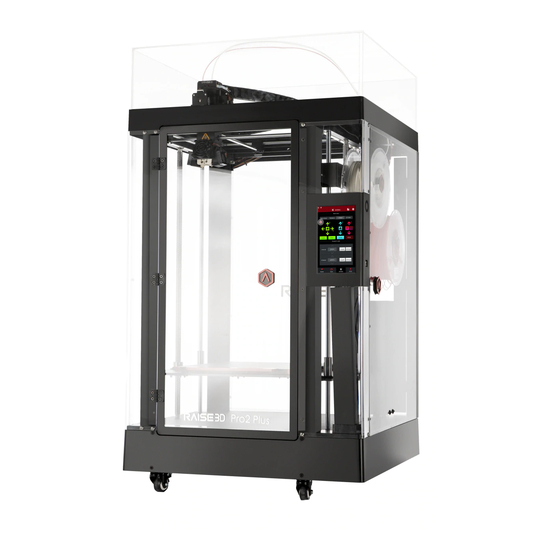
Raise3D Pro2 Manual
Hide thumbs
Also See for Pro2:
- Manual (43 pages) ,
- Quick start manual (32 pages) ,
- Installation instruction (5 pages)
Summary of Contents for Raise3D Pro2
- Page 1 Rev: V1.0 3D Printer Manual RAISE3D PRO2 SERIES www.raise3d.com Shanghai Fusion Tech Co., Ltd. 4th Floor, B5 Building, No.1600 Guoquan N Rd, Shanghai, China 200438...
-
Page 2: Table Of Contents
CONTENTS CONTENTS Safty ......................1 Electromagnetic Compatibility-EMC ............5 Technical Specifications – Pro2 / Pro2 Plus ..........7 Printer Components ..................8 Spare Parts ....................10 Hardware Installation ................10 Operation ....................15 Wire Diagram .................... 16 WWW.RAISE3D.COM AMERICA · ASIA · EUROPE... -
Page 3: Safty
SAFTY Warning: Indicates a potentially hazardous situation which, if not avoided, may result in injury or damage. Hot Nozzle: The hot nozzle sign indicates the presence of devices with high temperatures. Always use extra care when working around heated components. Always wear the heat resistant gloves provided in the Starter Box. -
Page 4: Electromagnetic Compatibility-Emc
Electromagnetic Compatibility-EMC Simplified EU Declaration of Conformity Pro2/Pro2 Plus declares that this device is in compliance with the essential requirements and other relevant provision of Directive 2014/53/EU.Full tex of EU declaration of conformity is available at https://www.raise3d.com The WIFI operation in the band 5150-5250MHz shall be restricted to indoor use for countries listed in the table... - Page 5 This equipment should be installed and operated with minimum distance 20cm between the radiator & your body. Changes or modifications not expressly approved by the party responsible for compliance could void the user’s authority to operate the equipment. WWW.RAISE3D.COM AMERICA · ASIA · EUROPE...
-
Page 6: Technical Specifications - Pro2 / Pro2 Plus
TECHNICAL SPECIFICATIONS Technical Specifications – Pro2 / Pro2 Plus Item Pro2 Pro2 Plus Power Supply Input 100-240 VAC, 50/60 Hz 230V@3.3A Power Supply Output 24VDC 600W User Interface Controller Freescale imx6, Quad core 1Ghz ARM processor Ports SD card*1, USB 2.0*2, Ethernet*1 Ethernet 802.11b/g/n... -
Page 7: Printer Components
COMPONENTS AND PARTS Printer Components and Parts 1. Front Parts Filament Run-out Sensor That can detect whether filament has been run out. Filament Feeder That’s part includes feeder motor and gear mechanical. Hot Ends The hotend is made up of Nozzle,heater block, thermocouple, heater cartridge and heat sink. Nozzle WARNING temperatures in the printer can exceed 300℃(572℉). - Page 8 The parts can drive Z stage’s movement. E USB storage slots F Power inlet and Power switch That is the power supply unit. A 250V 10A fuse is located to protect the input power. 3. Bottom Parts. WWW.RAISE3D.COM AMERICA · ASIA · EUROPE...
- Page 9 COMPONENENTS AND PARTS 4. Electrical Parts WWW.RAISE3D.COM AMERICA · ASIA · EUROPE...
-
Page 10: Spare Parts
SPARE PARTS Spare Parts... - Page 11 PRECAUTION AND INSTALLATION Read the entire installation section before starting installation. AWARNING Connect equipment to a grounded facility power source. Do not defeat or bypass the ground lead. • Know the location of equipment branch circuit interrupters or circuit breakers and how to turn them on and off in case of emergency.
-
Page 12: Hardware Installation
Make sure the amount of power available from the input connection is adequate for normal operation of the machine. After connecting the input cord to the machine, make the power switch on, the Pro2 / Pro2 Plus printer will start to work. - Page 13 Go to "Utilities" and press Z homing button to home the Z print bed to origin position. Take the starter box and filament box out from the base of the printer. And open for standby. WWW.RAISE3D.COM AMERICA · ASIA · EUROPE...
- Page 14 50mm. Loose the two thumb screws in front of the build plate with anti-clockwise rotation. Take build plate off from the protective cover. Please remove the leveling testing model carefully from the build plate. WWW.RAISE3D.COM AMERICA · ASIA · EUROPE...
- Page 15 PRECAUTION AND INSTALLATION Slide the build plate onto the Z platform. Face the surface with Raise3D logo up. Re-install the thumb screws back with clockwise rotation. Install the filament holder in the mount point on the side of the printer and place a spool of filament on the holder.
- Page 16 “Load” button. Finish the feeding operation step by step according to the instructions on the screen. NOTE: This document is set based on the Raise3D PLA filament, which is delivered together with the printer. Therefore we advise that you use this PLA for testing. WWW.RAISE3D.COM...
-
Page 17: Operation
OPERATION Operation Even though Pro2/Pro2 Plus is preleveled in the factory, please press X/Y axis ‘home’ button first and then Z axis 'home' button to check whether the leveling is changed during shipping. Select "10mm" for "Move Steps" and move X to 50mm, Y to 10mm. - Page 18 You can choose a network to join by inputting the password. When the WIFI module is manufactured, 2.4G is set at HT20, 5GHz is set at HT40. The wifi’s frequency is fixed before being manufactured. The customer is not allowed to modified WIFI’s parameter. If there’s needed, please connect Raise 3D. WWW.RAISE3D.COM AMERICA · ASIA · EUROPE...
- Page 19 OPERATION Or Add Other Network with inputting its name and password. Figure 1.40: Inputting Network’s Name WWW.RAISE3D.COM AMERICA · ASIA · EUROPE...
-
Page 20: Wire Diagram
WIRE DIAGRAM Wire Diagram PRO2 / Pro2 Plus WIRE DIAGRAM SCREEN BOARD Antenna WIFI -12V+ -12V+ -12V+ SCREEN CAERA MOTION CONTROL BOARD +24V- +24V- +24V- Extruder board Raise3d... - Page 21 NOTES WWW.RAISE3D.COM AMERICA · ASIA · EUROPE...


Need help?
Do you have a question about the Pro2 and is the answer not in the manual?
Questions and answers