Table of Contents
Advertisement
Quick Links
Advertisement
Table of Contents

Related Manuals for GST GST-IFP4M


Summary of Contents for GST GST-IFP4M
-
Page 2: Table Of Contents
1.4.9 CA-400-R CA-400-W or CA-400-G Cabinet ............8 1.4.10 P-9983 Fiber-Optical Network Card ..............8 1.4.11 P-9956-Modbus Modbus Card ................ 8 1.4.12 GST-BAT65-R GST-BAT65-W GST-BAT65-G Battery Box ......9 1.5 Peripheral Devices ....................9 Accessories ......................... 10 1.6 Defining Tool ......................11 2 Installation ........................ - Page 3 2.5.8 Optical Network Connection ................32 2.5.9 Hybrid Network Connection ................33 2.5.10 Modbus Card Connection ................33 2.5.11 GST-MP Voice Evacuation System Master Panel ......... 34 2.5.12 GST-MNA2C/GST-MNA2F Network Annunciator .......... 34 2.5.13 UL Power-limited Wiring Requirements ............35 2.6 Connection Inspection ...................
- Page 4 GST-IFP4M Intelligent Fire Alarm Control Panel Installation and Operation Manual 4.3.6 Day/Night Mode ....................69 4.3.7 Language Setup ....................70 4.3.8 Project Information ..................71 5 Equipment operation and information browsing ............ 72 5.1 Equipment operation ..................... 72 5.2 Devices information Browsing ................74 5.3 Record Browsing ....................
- Page 5 GST-IFP4M Intelligent Fire Alarm Control Panel Installation and Operation Manual Appendix D Battery Calculations ................. 91 Appendix E Operating Instructions ................94 Limited Warranty ......................95 Page...
-
Page 6: Fire Alarm System Limitations
GST-IFP4M Intelligent Fire Alarm Control Panel Installation and Operation Manual Fire Alarm System Limitations While a fire alarm system may lower insurance rates, it is not a substitute for fire insurance! An automatic fire alarm system – typically made up of smoke detectors, heat detectors, manual pull stations, Notification Appliances, and a fire alarm control with remote notification capability–can provide early warning of a developing fire. - Page 7 GST-IFP4M Intelligent Fire Alarm Control Panel Installation and Operation Manual Smoke detectors cannot be expected to provide adequate warning of fires caused by arson, children playing with matches (especially in bedrooms), smoking in bed, and violent explosions (caused by escaping gas, improper storage of flammable materials, etc.).
-
Page 8: Installation Precautions
GST-IFP4M Intelligent Fire Alarm Control Panel Installation and Operation Manual Installation Precautions Adherence to the following will aid in problem-free installation with long-term reliability: WARNING - Several different sources of power can be connected to the fire alarm FACP. Disconnect all sources of power before servicing. Control unit and associated equipment may be damaged by removing and/or inserting cards, modules, or interconnecting cables while the unit is energized. - Page 9 GST-IFP4M Intelligent Fire Alarm Control Panel Installation and Operation Manual Before proceeding, the installer should be familiar with the following documents. NFPA Standards NFPA 72 National Fire Alarm Code NFPA 70 National Electrical Code Underwriters Laboratories Documents: ...
-
Page 10: Notices
GST-IFP4M Intelligent Fire Alarm Control Panel Installation and Operation Manual Notices NOTICE TO USERS, INSTALLERS, AUTHORITIES HAVING JURISDICTION, AND OTHER INVOLVED PARTIES: This product incorporates field-programmable software. In order for the product to comply with the requirements in the Standard for Control Units and Accessories for Fire Alarm Systems, UL 864, certain programming features or options must be limited to specific values or not used at all as indicated below. -
Page 11: Product Introduction
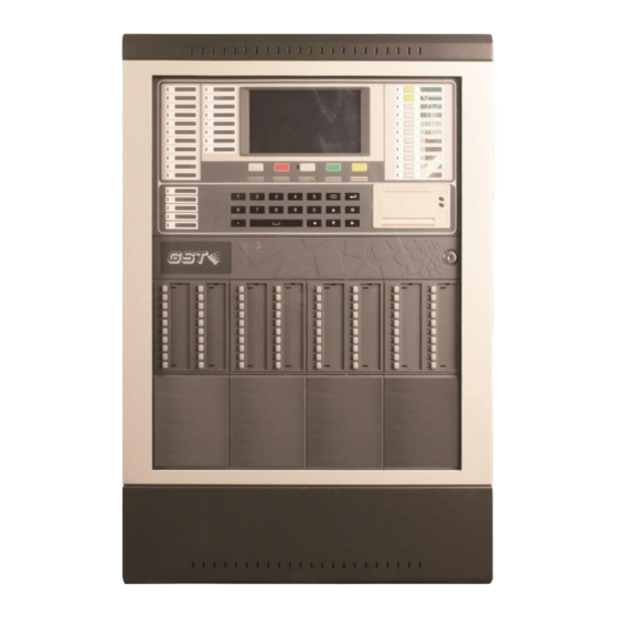
Installation and Operation Manual Product Introduction GST-IFP4M is an Intelligent Fire Alarm Control Panel (FACP) designed for medium- to large-scale facilities. It complies to UL 864 standard with features of easy installation, operation, and maintenance. The FACP integrates an ARM7-Cotex CPU with inbuilt Linux OS. -
Page 12: Basic Components
GST-IFP4M Intelligent Fire Alarm Control Panel Installation and Operation Manual The electrical limitations of the system power supply. The capacity of the secondary power source (standby batteries). 1.3 Basic Components A basic FACP requires at least the following components: ... -
Page 13: P-9981 Zone Display Panel
CA-400-W Cabinet is white and the CA-400-G is gray. 1.4.10 P-9983 Fiber-Optical Network Card P-9983 card is optional for GST-IFP4M control panel, providing two LC single-mode fiber interfaces. This card provides the same function as P-9966A CAN Class A network card. -
Page 14: Gst-Bat65-R Gst-Bat65-W Gst-Bat65-G Battery Box
The battery with large capacity can be placed in the box. The largest capacity for the battery in the box is 65Ah. The GST-BAT65-R is red, GST-BAT65-W is white and the GST-BAT65-G is gray. 1.5 Peripheral Devices The following tables list all the devices available for the FACP. -
Page 15: Accessories
GST-IFP4M Intelligent Fire Alarm Control Panel Installation and Operation Manual DI-M9301 Digital Single Input and Output Module DI-M9305 Digital Single Riser Output Module Table4 Digital Zone Monitor Module Type Description DI-M9319 Digital Zone Monitor Module Table5 Loop Isolator Module Type... -
Page 16: Defining Tool
The handheld programmer has to be separately ordered. 1.6 Defining Tool GST-IFPx-Def Defining Tool is used for setting panel and network configuration, editing and downloading definition of device and C&E equation. Before the system starts operation, you need to set panel and network configuration, define the device and C&E using this software on a computer, and then download them to the FACP. -
Page 17: Installation
Power up the FACP and check if it can be normally started. External connection. Check the lines. Setup FACP and define devices using GST-IFPx-Def Defining Tool on a PC and download them to the FACP according to engineering configuration. Check and commission peripheral devices. - Page 18 GST-IFP4M Intelligent Fire Alarm Control Panel Installation and Operation Manual dimensions illustrated in following Fig 2.1. Fig 2.1 Install three fasteners in the wall with the screw heads protruding. Using upper ‘keyhole’ place back box over the three screws, level and secure.
-
Page 19: Install The Cabinet Of Battery
GST-IFP4M Intelligent Fire Alarm Control Panel Installation and Operation Manual Fig 2.2 2.2.2 Install the cabinet of battery User needs the external cabinet of battery when battery capacity is more than 38Ah.The battery cabinet is installed below the panel cabinet as Fig 2.3. The wiring from battery cabinet is connected to panel through knockout. - Page 20 GST-IFP4M Intelligent Fire Alarm Control Panel Installation and Operation Manual Fig 2.3 Fig 2.4 Page...
-
Page 21: Install Components
GST-IFP4M Intelligent Fire Alarm Control Panel Installation and Operation Manual Fig 2.5 2.3 Install Components WARNING: Disconnect all sources of power before servicing. The panel and associated equipment may be damaged by removing and/or inserting cards, modules or interconnecting cables while this unit is energized. - Page 22 GST-IFP4M Intelligent Fire Alarm Control Panel Installation and Operation Manual Fig 2.6 First, put two batteries on the right bottom side of the cabinet, then align the holes of battery holders with the holes on the cabinet, finally, fasten the battery holders through screws.
-
Page 23: Installing Circuit Modules
GST-IFP4M Intelligent Fire Alarm Control Panel Installation and Operation Manual Fig 2.7 WARNING: Battery contains sulfuric acid, which can cause severe burns to the skin and eyes and can destroy fabrics. If contact is made with sulfuric acid, immediately flush the skin or eyes with water for 15 minutes and seek immediate medical attention. - Page 24 GST-IFP4M Intelligent Fire Alarm Control Panel Installation and Operation Manual Fig 2.9 Fig 2.10 First, aligh the circuit module (board) with the slot inside the cabinet; Second, slide down two sides of the circuit board along the guide rail; Third, press it down to the end and lock it by pressing small buttons on the two sides.
-
Page 25: Installing Zone Display And Control Panel
GST-IFP4M Intelligent Fire Alarm Control Panel Installation and Operation Manual Fig 2.11 First, pinch small two buttons; Second, Pull them up to unlock; Third, Continue to pull up with strength. Finally, the board is disassembled. 2.3.3 Installing Zone Display and Control Panel Zone display and control panel is installed on the cabinet door. - Page 26 GST-IFP4M Intelligent Fire Alarm Control Panel Installation and Operation Manual Fig 2.12 First, Align the snap of the zone display and control panle with the slot on the door; Second, Hook the zone display and control panel with the door; Finally, fix the panel with screws.
-
Page 27: Installing Glass Door
GST-IFP4M Intelligent Fire Alarm Control Panel Installation and Operation Manual 2.3.4 Installing Glass Door The following Fig 2.13 to Fig 2.15 shows how to install the glass door on the cabinet. Fig 2.13 Fig 2.14 Page... -
Page 28: Installation Of Labels On The Front Panel
GST-IFP4M Intelligent Fire Alarm Control Panel Installation and Operation Manual Fig 2.15 Put the glass door on the cabinet after pulling down the latch which is on the left upper corner of the glass door. The glass door is installed after releasing the latch and making it go through the latch hole. - Page 29 GST-IFP4M Intelligent Fire Alarm Control Panel Installation and Operation Manual Fig 2.17 Fig 2.18 Page...
-
Page 30: Installation Of Labels On The Zone Display And Control Panel (Zcp)
GST-IFP4M Intelligent Fire Alarm Control Panel Installation and Operation Manual Fig 2.19 Take the front panel from the cabinet door as shown in Fig 2.16. The lable is inserted along the lead-in groove(as shown in Fig 2.17) after aligning the label with the label hole. -
Page 31: Start-Up Check
Powering on the FACP, LCD doesn’t light and all LEDs are illuminated for 5s. As All LED go out, LCD displays Data Loading…… and GST logo. Initiation of the system takes about 85s~90s. Self-test of LEDs on the front panel and ZCPs. -
Page 32: Battery Connection
GST-IFP4M Intelligent Fire Alarm Control Panel Installation and Operation Manual AC-DC Switch Power YELLOW/GREEN 120VAC / 60Hz BLUE 220VAC / 50Hz BROWN CIRCUIT BREAKER Fig 2.21 Note: Verify all cables are correctly connected before connecting power supply. Please make sure the mains power is in line with the rated voltage marked on the panel’s label. -
Page 33: Signaling Line Circuits (Slc) Connection
GST-IFP4M Intelligent Fire Alarm Control Panel Installation and Operation Manual between the batteries is not connected. Do not connect the interconnect cable until the system is completely installed. Observe polarity when connecting the batteries. The FUSE can be found in the accessories of panel. -
Page 34: Notification Appliance Circuits (Nac) Note: Synchronization Of The Audible And Visible Alarm Signal Is Only Provided On A Notification Circuit Basis Or On A Di-M9305 Controlled Zone Basis
GST-IFP4M Intelligent Fire Alarm Control Panel Installation and Operation Manual Detector Detector SLCx Detector Detector Fig2.24 2.5.4 Notification Appliance Circuits (NAC) Note: Synchronization of the audible and visible alarm signal is only provided on a notification circuit basis or on a DI-M9305 controlled zone basis. - Page 35 GST-IFP4M Intelligent Fire Alarm Control Panel Installation and Operation Manual 2.5.4.1 Connecting Strobes/Horns directly on NAC1 and/or NAC2 When NAC1 or NAC2/AUX is connected with Horns / Strobes directly, it needs to work in NAC synch Mode (Refer to Fig4.9 for the setting method). Connection of NAC is shown below Fig 2.27.
-
Page 36: Relays
GST-IFP4M Intelligent Fire Alarm Control Panel Installation and Operation Manual DI-M9305 DI-M9305 SLCx SLCx FACP 1KΩ(PartNo. 30108576) O1O2 O1O2 Strobes Strobes Horn/Strobes Horn/Strobes 47KΩ(PartNo 47KΩ(PartNo .30107534) .30107534) Fig 2.29 For NAC solution using DI-M9305 above, when a system is intended to provide signaling... -
Page 37: Can Network Connection
GST-IFP4M Intelligent Fire Alarm Control Panel Installation and Operation Manual INPUT Action Fig 2.31 This interface can only be used non-fire, non-emergency input, e.g. door status sensor. 2.5.7 CAN Network Connection P-9966A CAN Network Card can be plugged into L5/L6, S1 or S2 slot of MB-400 Mother Board. -
Page 38: Hybrid Network Connection
Network Cards are plugged into S1 and L5/L6. No1 GST-IFP4M and No2 GST-IFP4M make up a CAN network. At the same time, No1 GST-IFP4M and No3 GST-IFP4M make up a CAN network also. As a P-9983 is plugged into S2,a fiber network can be made up by No1 GST-IFP4M and No4 GST-IFP4M. -
Page 39: Gst-Mp Voice Evacuation System Master Panel
2.5.11 GST-MP Voice Evacuation System Master Panel GST-IFP4M control panel can connect with GST-MP Voice Evacuation System Master Panel through RS232. The wiring between the control panel and ASC card of GST-MP Voice Evacuation System Master Panel is shown in Fig 2.37. Interconnecting wires shall be installed within conduit and maximum Length shall NOT exceed 20 feet, and GST-IFP4M can send Alarm signals to GST-MP. -
Page 40: Ul Power-Limited Wiring Requirements
GST-IFP4M Intelligent Fire Alarm Control Panel Installation and Operation Manual MAX 250 nodes CALSS A The distance between two neighbor nodes is less than 3000m; Twisted pair with cross section 18AWG (0.82mm Maximum 250 NETWORK Annunciators Or... - Page 41 GST-IFP4M Intelligent Fire Alarm Control Panel Installation and Operation Manual Fig 2.39 Fig 2.40 Page...
-
Page 42: Connection Inspection
GST-IFP4M Intelligent Fire Alarm Control Panel Installation and Operation Manual 2.6 Connection Inspection Check the circuit connected with the FACP. Measure the insulation resistance between loops and between loops and ground, which should be more than 20MΩ. Measure the load of detection loops, which should be more than 1kΩ. The resistance between cables of NAC1, NAC2 should be equal to the end-of-line resistance (4.7kΩ). -
Page 43: Indication & Control
GST-IFP4M Intelligent Fire Alarm Control Panel Installation and Operation Manual Indication & Control The keys and LED indicators of FACP are shown below Fig3.1. Fig3.1 3.1 LED Indicators Note: Unless otherwise specified, all LEDs are yellow. Except for POWER LED, all LEDs go out when the FACP is reset. - Page 44 GST-IFP4M Intelligent Fire Alarm Control Panel Installation and Operation Manual NAC2TROUBLE/DIS: This LED is enabled when NAC2/AUX output is programmed as “NAC” (See Fig 4.10). It lights when NAC2 port is fault; it goes out as the fault is removed.
-
Page 45: Functional Keys
GST-IFP4M Intelligent Fire Alarm Control Panel Installation and Operation Manual RESET: It lights when the FACP is being reset; It goes out when the FACP completes reset. ☼/☪ SWITCH: It lights when the FACP is in Night mode; it goes out in Day mode. -
Page 46: Service / Program Keys
GST-IFP4M Intelligent Fire Alarm Control Panel Installation and Operation Manual indication of restoration to normal condition. For non-latching supervisory, the signal will be locked-in until manually reset. Supervisory information screen is displayed when there is supervisory information and this key is pressed. -
Page 47: User Interface
GST-IFP4M Intelligent Fire Alarm Control Panel Installation and Operation Manual LEFT cursor. Press this key to switch the cursor to previous box or select options to the left. CANCEL key. Press this key to cancel an operation or exit a menu. - Page 48 GST-IFP4M Intelligent Fire Alarm Control Panel Installation and Operation Manual Fig 3.4 When there are multiple fire alarms, the Alarm tab will display all zones that are in alarm. If one of the zones in fire is clicked, the next screen will appear to show all devices with fire alarm in that zone.
- Page 49 GST-IFP4M Intelligent Fire Alarm Control Panel Installation and Operation Manual DISABLE tab can view the details as shown in the figure below Fig 3.5. STATUS: clicking STATUS tab can view other status messages of the FACP. Page...
-
Page 50: Operations
GST-IFP4M Intelligent Fire Alarm Control Panel Installation and Operation Manual 4 Operations 4.1 Programming on FACP Configurations and definitions can also be programmed directly on the FACP. Clicking the button inputs engineering password to enter Panel Setup menu (tree diagram) as shown below Fig 4.1. - Page 51 GST-IFP4M Intelligent Fire Alarm Control Panel Installation and Operation Manual Fig 4.2 Password: clicking Password in Basic Setting menu enters the screen for setting passwords as shown in the figure below Fig 4.3. There are two types of passwords including User Password and Engineering Password.
- Page 52 GST-IFP4M Intelligent Fire Alarm Control Panel Installation and Operation Manual Fig 4.5 Clicking Undefined can define LEDs and buttons as shown in Fig 4.6. Fig 4.6 I/O Interface: clicking I/O Interface in Basic Setting menu, all output interfaces are displayed on the right of the screen and users can edit each interface specifically.
- Page 53 GST-IFP4M Intelligent Fire Alarm Control Panel Installation and Operation Manual NAC: Clicking NAC enters the screen of setting NAC1. There are two programmable settings for NAC1:Coding and Silenceable. Refer to the following figure Fig 4.8. Fig 4.8 The Coding feature allows the user to select the type of output that NAC1 will generate when activated.
- Page 54 GST-IFP4M Intelligent Fire Alarm Control Panel Installation and Operation Manual “Resettable” option as shown on Fig 4.10 below. Fig 4.10 AUX SYNC mode is to be used to provide a synchronized NAC power source for notification appliances controlled by DI-M9305 Single Riser Output Module. Refer to 2.5.4.3.
-
Page 55: Program
GST-IFP4M Intelligent Fire Alarm Control Panel Installation and Operation Manual Fig 4.12 Sometimes users do not want detectors become too dirty to alarm. User can enter the screen setting loop devices following path: Panel Setup->Programme->Loops. Clicking a certain loop, a list for the loop will be shown. - Page 56 GST-IFP4M Intelligent Fire Alarm Control Panel Installation and Operation Manual Fig 4.14 Fast Location: The related zone can be located by inputting a number. Click the plus sign (+) to add a new zone, or double-click the existed zone to edit the selected zone.
- Page 57 GST-IFP4M Intelligent Fire Alarm Control Panel Installation and Operation Manual Fig 4.16 Adding the button in ZCP for individual “Silence” and “Resound” can control the Horn / Strobes in this zone independently. Loops: clicking Loops enters the screen for setting loop devices. The right screen shows all the loops of the FACP, quantity of devices of each loop, as shown in the figure below Fig 4.17.
- Page 58 GST-IFP4M Intelligent Fire Alarm Control Panel Installation and Operation Manual Fig 4.18 Add/Delete a Device: clicking Add or Del button on the right corner, devices can be added or deleted. Refer to the following figure Fig 4.19. Fig 4.19 Clicking a device in device define screen pops up the screen for setting the device in details.
- Page 59 GST-IFP4M Intelligent Fire Alarm Control Panel Installation and Operation Manual Panel: address of the FACP Loop: loop number of the device Address: address code of the device Reg State: status of the device Zone: zone number of the device ...
- Page 60 GST-IFP4M Intelligent Fire Alarm Control Panel Installation and Operation Manual Clicking a cause and effect matrix of any kind, details of that kind of matrix can be shown as in Fig 4.22. Fig 4.22 Clicking Find in Fig 4.22 can pop up a dialogue box as shown in Fig 4.23. As the conditions are changed as required, clicking OK can view those cause and effect matrixes meeting those conditions.
- Page 61 GST-IFP4M Intelligent Fire Alarm Control Panel Installation and Operation Manual Fig 4.24 Clicking a device in the list, drag and release it in the editing area. A new matrix will be added by editing the parameters. Selecting a device in editing area, its message can be changed by clicking Edit or double clicking on the device.
- Page 62 GST-IFP4M Intelligent Fire Alarm Control Panel Installation and Operation Manual Fig4.26 ZCP: clicking ZCP in Programme menu enters the screen for setting the zone display and control panels. Refer to the figure below Fig 4.27. Fig 4.27 Click on a ZCP No enters the setting screen as shown in the figure below Fig 4.28.
- Page 63 GST-IFP4M Intelligent Fire Alarm Control Panel Installation and Operation Manual Fig 4.28 Individual NAC zone can be controlled by DI-M9305 modules (Device Type: 13 ) connected to SLC. Refer to the figure below Fig 4.29 for the setting method. Fig 4.29 Then add the button in ZCP for individual “Silence”...
- Page 64 GST-IFP4M Intelligent Fire Alarm Control Panel Installation and Operation Manual Then, add the lamp of individual “Silence” and the lamp of individual “activation”. Refer to the figure below Fig 4.31. Fig 4.31 Network: clicking Network in Programme menu enters the screen for checking the network topology of the whole system.
-
Page 65: Advanced Setting
GST-IFP4M Intelligent Fire Alarm Control Panel Installation and Operation Manual sub-nets are listed in line as shown in Fig 4.32. For the first line: Main (Local: 5) 17-250-10-17 Qty:003/009 Main (Local: 5): Main net, Local: 5 is the address of current panel. - Page 66 GST-IFP4M Intelligent Fire Alarm Control Panel Installation and Operation Manual Fig 4.34 Loop ID: loop No. Original Address: an existing device code. New Address: a new device code. Delay Setting: Users can set delay based on the actual situation by clicking Delay Setting in Advanced Setting menu as shown in Fig 4.35.
-
Page 67: Programming The Facp Through Gst-Ifpx-Def Defining Tool
4.2 Programming the FACP Through GST-IFPx-Def Defining Tool Configurations and definitions can be downloaded to the FACP through USB or Ethernet interfaces after they are programmed by using GST-IFPx-Def (version 1.0 or above) Defining Tool. 4.2.1 Download thru USB interface... -
Page 68: Download Thru Ethernet Interface ( The External Computer Connected Must Be Located At The Same Room With The Control Panel )
So, the control panel is added with a function that can be locked or unlocked through GST-IFPx-Def Defining Tool. USB Dongle is purchased from us to protect data not modifing by random. -
Page 69: Bacnet ( The External Device Connected Must Be Located At The Same Room With The Control Panel )
GST-IFP4M Intelligent Fire Alarm Control Panel Installation and Operation Manual Center software on the computer and get authorization by using USB dongle. After authorization, he can read history records, status of panels and bus devices to find and solve the problems. - Page 70 GST-IFP4M Intelligent Fire Alarm Control Panel Installation and Operation Manual Fig 4.42 Pressing ”Back” can return and get BACnet added. Fig 4.43 Clicking ”BACnet” enters the screen for setup. Fig 4.44 BACnet: Enable (on) Bacnet or not. Page...
-
Page 71: Cpu Backup
GST-IFP4M Intelligent Fire Alarm Control Panel Installation and Operation Manual Recipient Device Id: ID of receiving devices. Recipient IP Address: IP of receiving devices. (set one of ID or IP) Broadcast: Broadcast or not. Save: Save or not. Fig 4.45 4.2.6 CPU Backup... -
Page 72: User Setup
GST-IFP4M Intelligent Fire Alarm Control Panel Installation and Operation Manual 4.3 User Setup Clicking button enters User Setup menu by inputting user password. Messages about soft keyboard, display, PAS, clock, printer, day/night mode, language, project name, and so can be set in this screen. Refer to the figure below Fig 4.47. -
Page 73: Clock Setup
GST-IFP4M Intelligent Fire Alarm Control Panel Installation and Operation Manual Activate NAC in Test Mode: UL listed notification appliances are connected to the NACs. User can set the activate time of notification appliances in test mode by the option. Fig4.49 4.3.4 Clock Setup... -
Page 74: Print Setup
GST-IFP4M Intelligent Fire Alarm Control Panel Installation and Operation Manual Fig 4.51 4.3.5 Print Setup Clicking Print Setup in User Setup menu enters the screen for setting the printer. Real-time print and printing types can be set. Refer to the figure below Fig 4.52. -
Page 75: Language Setup
GST-IFP4M Intelligent Fire Alarm Control Panel Installation and Operation Manual Fig 4.53 In this mode, starting and ending time for the day can be set. Refer to the following figure Fig 4.54. Fig 4.54 4.3.7 Language Setup Clicking Language Setup in User Setup menu enters the screen for setting the language. -
Page 76: Project Information
GST-IFP4M Intelligent Fire Alarm Control Panel Installation and Operation Manual Fig 4.55 4.3.8 Project Information Clicking Project Information in User Setup menu enters the screen for setting the project information. Refer to the figure below Fig 4.56. Fig 4.56 Page... -
Page 77: Equipment Operation And Information Browsing
GST-IFP4M Intelligent Fire Alarm Control Panel Installation and Operation Manual 5 Equipment operation and information browsing 5.1 Equipment operation Clicking button on the left corner enters the menu for operating device including Reset, Mute, Silence, Self Check, Start, Stop, Disable and Enable. Refer to the following figure Fig 5.1. - Page 78 GST-IFP4M Intelligent Fire Alarm Control Panel Installation and Operation Manual in Fig5.3. Choosing device type and then clicking OK can confirm to start these devices in this zone. Fig 5.3 Start Device: starting a designated device. Clicking Start Device enters the screen shown below Fig 5.4.
-
Page 79: Devices Information Browsing
GST-IFP4M Intelligent Fire Alarm Control Panel Installation and Operation Manual Fig 5.5 Start Sounder: Clicking Start Sounder enters the screen for starting sounders. Choosing a designated zone and then clicking OK can confirm to start all sounders in the zone. - Page 80 GST-IFP4M Intelligent Fire Alarm Control Panel Installation and Operation Manual the figure below Fig5.7. Fig 5.7 Panel Configuration: clicking Panel Configuration can browse the hardware versions and firmware versions of all boards. Zones: clicking Zones can browse all loop devices by zone. Device browsing screen is the same as the editing screen, but the function is different.
- Page 81 GST-IFP4M Intelligent Fire Alarm Control Panel Installation and Operation Manual Fig 5.7.1 Clicking Net View enters the screen below for browsing network control panels. Fig 5.7.2 Panel: Filling in panel number to be browsed. Type: Filling in information type including Card, Loop, ZCP, and Formula.
- Page 82 GST-IFP4M Intelligent Fire Alarm Control Panel Installation and Operation Manual In Fig. 5.7.4 shows the information of Loop type is browsed. Fig 5.7.4 Clicking Confirm can enter the screen below. Fig 5.7.5 In Fig. 5.7.6 shows the information of ZCP type is browsed.
- Page 83 GST-IFP4M Intelligent Fire Alarm Control Panel Installation and Operation Manual Fig 5.7.6 ZCP No: Fill in ZCP number to be browsed, and then press Confirm to enter the screen below. Fig 5.7.7 Browsing the information of Formula type is shown in Fig. 5.7.8.
-
Page 84: Record Browsing
GST-IFP4M Intelligent Fire Alarm Control Panel Installation and Operation Manual Fig 5.7.8 C&E Type: Fill C&E formula type and C&E formula No.,and then press Confirm to browse the screen below. Fig 5.7.9 5.3 Record Browsing Clicking button on the left corner enters the screen for browsing history record. - Page 85 GST-IFP4M Intelligent Fire Alarm Control Panel Installation and Operation Manual Fig 5.8 Each message includes Time, Event Type, Code, Device Type, Details and Panel. Page...
-
Page 86: Operating Instructions
GST-IFP4M Intelligent Fire Alarm Control Panel Installation and Operation Manual 6 Operating Instructions 6.1 Panel Control Keys 6.1.1 ACKNOWLEDGE (User password) Pressing ACKNOWLEDGE key will acknowledge a new fire, fault, or supervisory event. Pressing ACKNOWLEDGE key will result in the following actions: ... -
Page 87: Positive Alarm Sequence
GST-IFP4M Intelligent Fire Alarm Control Panel Installation and Operation Manual 6.2 Positive Alarm Sequence Positive Alarm Sequence (PAS) procedure: When a detector alarms, sound indication of the FACP shall be started immediately and PAS delay devices shall be activated. ... -
Page 88: Default Programming
GST-IFP4M Intelligent Fire Alarm Control Panel Installation and Operation Manual 7 Default Programming Program Option Factory Default BANNER GST CO., LTD. Maintenance Password Empty User Password 111111 PAS Timer Userwords Undefined Userdefine Userdefine01-15 E&C Undefined Device address(1-242) Zone: 001 Type: 0 Undefined... -
Page 89: Appendix A Basic System Connection
GST-IFP4M Intelligent Fire Alarm Control Panel Installation and Operation Manual Appendix A Basic System Connection Notification Appliance Circuit (Power-limited Circuit, Supervised, Class B) Signaling Line Circuit NAC1 & NAC2(NAC2/AUX pr ogrammed as NAC) (Power-limited Circuit, Super vised, The end-of-line resistor is 4.7kΩ(Part No. 3010 7866). -
Page 90: Appendix B Electrical Specifications
GST-IFP4M Intelligent Fire Alarm Control Panel Installation and Operation Manual Appendix B Electrical Specifications B.1 Electrical Specifications B.1.1 AC Power 120VAC, 60Hz, 3.0A (Maximum Alarm) 220VAC, 50Hz, 1.5A (Maximum Alarm) Wire size: Minimum 14AWG (2.0mm ) with 600V insulation. The FACP shall be connected to max branch circuit of 15A. -
Page 91: Relays
GST-IFP4M Intelligent Fire Alarm Control Panel Installation and Operation Manual Programmable as resettable or non-resettable Nominal operating voltage: 24VDC Maximum standby current: 0.25A Maximum signaling current: 2.5A (Shared by both NAC1 and NAC2/AUX) End-of-line resistor: 1kΩ (Part No. 30108576) B.1.6 Relays... - Page 92 GST-IFP4M Intelligent Fire Alarm Control Panel Installation and Operation Manual No. of MCPs No. of input modules No. of output modules No. of loop isolators Max. length 4000m 3300m 2600m 2000m with 14AWG Max. length 3500m 2700m 2200m 1700m with 15AWG Max.
-
Page 93: Appendix C Compatible Devices
GST-IFP4M Intelligent Fire Alarm Control Panel Installation and Operation Manual Appendix C Compatible Devices C.1 Series Addressable Detectors Intelligent, addressable detectors provide information to the FACP on an SLC (Signaling Line Circuit). This allows the FACP to continually monitor the status (alarm, trouble, maintenance or normal) of each detector. -
Page 94: Detector Bases
GST-IFP4M Intelligent Fire Alarm Control Panel Installation and Operation Manual Built-in MCU can store 14 history messages. Polling LED can be set to close. 2 levels smoke sensitivities programmable, complies with UL268. Heat part complies with UL521. -
Page 95: Horn / Strobes / Signal Synchronization Module
GST-IFP4M Intelligent Fire Alarm Control Panel Installation and Operation Manual C.5 Horn / Strobes / Signal Synchronization Module Strobes: UL listed DC-M9415W/ DC-M9415R manufactured by GST. Horns: UL listed DC-M9414W/ DC-M9414R manufactured by GST. Horns / Strobes: UL listed DC-M9413W/ DC-M9413R / DC-M9416W/ DC-M9416R manufactured by GST. - Page 96 GST-IFP4M Intelligent Fire Alarm Control Panel Installation and Operation Manual Appendix D Battery Calculations Power Requirements (All currents are in amperes) Total Total Model Type Description Qty. Standby Alarm Standby Alarm GST-IFP4M FACP 0.30 0.50 GST-IFP4M AUX Load (max.0.2 (max.0.2...
- Page 97 GST-IFP4M Intelligent Fire Alarm Control Panel Installation and Operation Manual Intelligent DI-M9102 Photoelectric 0.0008 0.0018 Smoke Detector Intelligent Rate of Rise and Fixed DI-M9103 0.0006 0.0015 Temperature Heat Detector Digital Manual Call DI-M9204 0.0006 0.0018 Point C-M9503 Loop Isolator 0.00015 0.00015...
- Page 98 GST-IFP4M Intelligent Fire Alarm Control Panel Installation and Operation Manual Innovation Manual DC-M9204 0.0006 0.0018 Call Point Digital Single Input DI-M9300 0.00026 0.0005 Module Digital Single Input DI-M9301 0.00028 0.0007 and Output Module Digital Zone Monitor DI-M9319 0.00038 0.00039 Module...
- Page 99 Appendix E Operating Instructions and supervisory events. If more than one event exists, the LCD displays Normal Standby the one of the highest level. Subsequent press of ACKNOWLEDGE shall With no alarm or trouble in the system, the display message is System switch between different messages, and pressing the UP and DOWN Normal.
- Page 100 Limited Warranty The manufacturer warrants its products to be free from defects in materials and workmanship for 2 years from the date of manufacture, under normal use and service. Products are date-stamped at time of manufacture. The sole and exclusive obligation of the manufacturer is to repair or replace, at its option, free of charge for parts and labor, any part which is defective in materials or workmanship under normal use and service.
- Page 101 Gulf Security Technology Co., Ltd. No. 80, Changjiang East Road, QETDZ, Qinhuangdao, Hebei, P. R. China 066004 Tel: +86 (0) 335 8502434 Fax: +86 (0) 335 8502532 service.gst@fs.utc.com www.gst.com.cn...
Need help?
Do you have a question about the GST-IFP4M and is the answer not in the manual?
Questions and answers
What is the default password