Table of Contents
Advertisement
Quick Links
Advertisement
Table of Contents

Related Manuals for GST GST303


Summary of Contents for GST GST303
-
Page 2: Table Of Contents
GST303 /GST306 Extinguishing Control Panel Installation and Operation Manual CONTENTS General ........................1 Features ........................1 Technical Specifications .................... 1 Structure and Operation Principle ................2 4.1 Structure ........................2 4.1.1 Front Panel ......................3 4.1.2 Internal Structure ....................4 4.2 Operation Principle ..................... -
Page 3: General
Except for 3 extinguishing zones less, and some minor differences in appearance and structure, GST303 is the same as GST306 in operation. We’ll take GST306 as an example. 2 Features... -
Page 4: Structure And Operation Principle
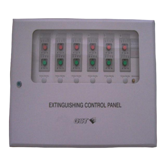
This control panel is surface-mounted on the wall. It contains main board, zone control board, I/O board, filter board, Start key, Stop key and Power switch, etc. Appearances of the GST303 and GST306 control panels are shown in Fig. 4-1. Fig. 4-1(a) -
Page 5: Front Panel
GST303 /GST306 Extinguishing Control Panel Installation and Operation Manual Fig. 4-1(b) 4.1.1 Front Panel Front panel of GST306 is consisted of start/stop control panel (including Start key, Stop key and indicators), Power switch, Reset switch, and Manual Start key as shown in Fig. -
Page 6: Internal Structure
GST303 /GST306 Extinguishing Control Panel Installation and Operation Manual immediate start and delay start) and remains illuminating after relay output is activated. Release Confirm LED: Red. It illuminates when corresponding zonal pressure switch is activated. Fault LED: Yellow. It illuminates when connecting cable between the control panel and emergency gas override control or gas release warning indicator is in short or open circuit;... - Page 7 GST303 /GST306 Extinguishing Control Panel Installation and Operation Manual Zone Control Zone Control Filter Board Board 6 Panel 1 Main Board Reset Power Switch Manual Disable I/O Board 6 I/O Board 1 Gas Stop Indicator Board D1 D2 Z1 Z2...
- Page 8 GST303 /GST306 Extinguishing Control Panel Installation and Operation Manual Main Board Fig. 4-5 ① Loop terminals, connecting with signal cable. ② Terminal for connecting with Manual Start control key. ③ 20P ribbon cable socket, connecting with zone control board. ④ 20P ribbon cable socket, connecting with I/O board.
- Page 9 GST303 /GST306 Extinguishing Control Panel Installation and Operation Manual Zone Control Board Fig. 4-6 ① 20P ribbon cable socket connecting with main board ② Setting pin for zone control board ③ 16P ribbon cable socket, connecting with I/O board ④...
-
Page 10: Operation Principle
GST303 /GST306 Extinguishing Control Panel Installation and Operation Manual 4.1.2.3 I/O Board I/O Board Fig. 4-7 ① 20P ribbon cable socket connecting with main board. ② Terminals connecting input and output. ③ Pins for setting gas extinguishing output mode: Pulse mode in open circuit, and electric level in short circuit. -
Page 11: Mounting
GST303 /GST306 Extinguishing Control Panel Installation and Operation Manual 5.2 Mounting GST303, GST306 are wall-mounted. Their dimensions are shown in Fig. 5-1a and Fig.5-1b. Installation Hole Knockout Hole Fig.5-1a Installation Hole Knockout Hole Fig. 5-1b When the conduit comes from the ceiling, the control panel is supported by a bracket. -
Page 12: Terminals
GST303 /GST306 Extinguishing Control Panel Installation and Operation Manual Conduit Cabinet Bracket Fig. 5-2 a) Cabinet Conduit Fig. 5-2 b) 5.3 Terminals All external wires are connected to the control panel through I/O board or filter. Terminals are shown in Fig. 5-3. -
Page 13: Wiring
GST303 /GST306 Extinguishing Control Panel Installation and Operation Manual DC1- DC1+ DC2- DC2+ YK2 SW2 SW1 Fig. 5-3 D1, D2: Power input, polarity-insensitive. Z1, Z2: FACP loop input terminal, polarity-insensitive. DC1-, DC1+: Extinguishing start terminal, to gas extinguishing relay module. -
Page 14: Setting
GST303 /GST306 Extinguishing Control Panel Installation and Operation Manual When there are several emergency gas override controls, they should be connected in series. (4) Sounder strobe are to be connected to the control panel by two-wire mode, to signal loop by polarity-insensitive two-wire, and to 24VDC power by polarity-insensitive two-wire. -
Page 15: Setting Delay Time
GST303 /GST306 Extinguishing Control Panel Installation and Operation Manual Table 1 Position of S1 Corresponding initial address After the initial address is set, the addresses of control enable pin, emergency start button, emergency stop button, gas extinguishment and addresses reserved for future use will be automatically set in sequence according to the number of zone control board. -
Page 16: Setting Control Command Output
GST303 /GST306 Extinguishing Control Panel Installation and Operation Manual Fig. 5-6 To set the delay time, you can open the enclosure and turn code switch S2 on the main board. The different position of S2 corresponds to different delay time as in Table 3. -
Page 17: Commission Of Delay Start
GST303 /GST306 Extinguishing Control Panel Installation and Operation Manual codes. After the system is properly connected (except for solenoid), do the whole commission. Use 24VDC relay in position of solenoid. 5.7.1 Commission of Delay Start Press emergency start button, In Delay LED is lit, sounder strobe acts; the FACP reports “Emergency start”... -
Page 18: Installation Of Protective Cover
GST303 /GST306 Extinguishing Control Panel Installation and Operation Manual dump” fault. Disconnect any cable between control panel and protection door, the FACP reports “Gas dump” fault. 5.8 Installation of Protective Cover After mounting and commission, install the protective cover for start key and stop key. - Page 19 GST303 /GST306 Extinguishing Control Panel Installation and Operation Manual When using the control panel, press the Start key corresponding to the alarming zone on the control panel to start extinguishing devices, and output starting level. Since the holding period for starting level is the same as the time you press the start key for pulse output mode, you will have to keep pressing the start key until gas starts to release.
-
Page 20: Stop
GST303 /GST306 Extinguishing Control Panel Installation and Operation Manual Delay start control can be realized through field emergency start button and the FACP. When field emergency start button of protected zone is pressed, the control panel will enter delay start stage and report action of emergency start button to the FACP. -
Page 21: Troubleshooting
GST303 /GST306 Extinguishing Control Panel Installation and Operation Manual When the cable between the control panel and solenoid of cylinder connecting with gas extinguishing control relay module is in short or open circuit, it reports common fault and output fault; and Common Fault and Output Fault LEDs are lit. - Page 22 GST303 /GST306 Extinguishing Control Panel Installation and Operation Manual seconds after the control panel is reset. Then the control panel will start audible and visual alarm and report fault with Emergency Start button. In this case, the Emergency Start button and the control panel have to be reset.
-
Page 23: Appendix 1: System Connection
GST303 /GST306 Extinguishing Control Panel Installation and Operation Manual Appendix 1: System Connection C-9316 C-9316 C-9316 4.7K Ω DOOR DOOR 4.7K Ω DOOR 4.7K Ω C-9317 C-9317 4.7K Ω DC1+ DC1+ Solenoid of Cylinder DC1- DC1- C-9329 Pressure Switch Driving device... -
Page 24: Appendix 2: How To Install Protective Cover
GST303 /GST306 Extinguishing Control Panel Installation and Operation Manual Appendix 2: How to Install Protective Cover 1) Aligning the two feet of the cover to the installation hole of the control panel, as in Fig. A-2 and Fig. A-3. Feet cover Fig. - Page 25 GST303 /GST306 Extinguishing Control Panel Installation and Operation Manual Push Fig. A-4 Tendons Fig. A-5 Note: Push the protective cover with balanced strength to ensure the two feet. enter the holes simultaneously. Otherwise the cover will be damaged. ...
-
Page 26: Appendix 3: How To Start And Stop The Control Panel
GST303 /GST306 Extinguishing Control Panel Installation and Operation Manual Appendix 3: How to Start and Stop the Control Panel 1) Covers are used to protect the start and stop key of the control panel in order to avoid unwanted operation. Press the center of the cover firmly as shown in Fig. - Page 27 GST303 /GST306 Extinguishing Control Panel Installation and Operation Manual Fig. A-8 Fig. A-9 Page 25...
- Page 28 Gulf Security Technology Co., Ltd. No. 80, Changjiang East Road, QETDZ, Qinhuangdao, Hebei, P. R. China 066004 Tel: +86 (0) 335 8502434 Fax: +86 (0) 335 8502532 service.gst@fs.utc.com www.gst.com.cn...
Need help?
Do you have a question about the GST303 and is the answer not in the manual?
Questions and answers