Table of Contents
Advertisement
Advertisement
Table of Contents

Related Manuals for GST GST102A


Summary of Contents for GST GST102A
- Page 2 GST102A/GST104A/GST108A/GST116A Conventional Fire Alarm Control Panel Installation and Operation Manual QUICK OPERATION GUIDE PANEL FAULT Press the “SILENCE BUZZER” button to silence the BUZZER: panel fault buzzer. For any of the below functions you must be in Access Level 2 mode Insert the 003 key and turn to the “ON”...
-
Page 3: Table Of Contents
1.3.3 Operating Indicators and Keys ................... 7 1.4 Configuration and Functions ....................8 1.4.1 Internal Components ....................8 1.4.2 Configuration and Functions of GST-116A ..............8 1.4.3 Configuration and Functions of GST-108A ..............9 1.4.4 Configuration and Functions of GST-104A..............9 1.4.5 Configuration and Functions of GST-102A .............. - Page 4 GST102A/GST104A/GST108A/GST116A Conventional Fire Alarm Control Panel Installation and Operation Manual 2.4 Zone Input Connection ....................17 2.4.1 Using end of line resistor ..................17 2.4.2 Using an Active End of Line Unit ................17 2.5 Sounder/Fire Alarm Output Connections................. 17 Chapter 3 System Setup ......................
- Page 5 GST102A/GST104A/GST108A/GST116A Conventional Fire Alarm Control Panel Installation and Operation Manual 4.1.1 State of Detection Zones ..................29 4.1.2 Alarm Output State ....................29 4.1.3 Sounder Outputs State ..................... 29 4.1.4 Safe State ......................... 29 4.1.5 Description of the Buzzer ..................30 4.1.6 Others........................
-
Page 6: Installation Precautions
GST102A/GST104A/GST108A/GST116A Conventional Fire Alarm Control Panel Installation and Operation Manual Installation Precautions Adherence to the following will aid in problem-free installation with long-term reliability: Do not attempt to install, service, or operate this unit until this manual is read and understood. -
Page 7: 54 Information
Output to fire alarm devices Outputs Output to fire alarm routing equipment 7.9.1 EN 54 The power supply of GST102A/104A/108A/116A complies with the following EN 54-4 √ requirements. Power Supply Functions EN 54-4 Clause Power supply from the main power source... -
Page 8: Chapter 1 Product Overview
GST102A/104A/108A/116A Conventional Fire Alarm Control Panel is designed in compliance with EN 54-2. It’s compatible with GST C-9403 Conventional Sounder Strobe designed by EN 54-3, C- 9103 Conventional Rate of Rise and Fixed Temperature Heat Detector by EN 54-5, C-9102 Conventional Photoelectric Smoke Detector by EN 54-7, and DC-9204 Conventional Manual Call Point by EN 54-11. -
Page 9: Batteries
GST102A/GST104A/GST108A/GST116A Conventional Fire Alarm Control Panel Installation and Operation Manual ☆☆☆☆☆☆☆☆☆☆☆☆☆☆☆☆☆☆☆☆☆☆☆☆☆☆☆☆☆☆☆☆☆☆☆☆☆☆☆ Note: External overcurrent protection device is required and should be installed near the equipment. ☆☆☆☆☆☆☆☆☆☆☆☆☆☆☆☆☆☆☆☆☆☆☆☆☆☆☆☆☆☆☆☆☆☆☆☆☆☆☆ 1.2.2 Batteries Minimum Operating Voltage: 21.5V Maximum Charging Current: 400mA Maximum Charging Voltage: 27.6V Battery Type: Sealed lead-acid battery ... -
Page 10: Input Interface
GST102A/GST104A/GST108A/GST116A Conventional Fire Alarm Control Panel Installation and Operation Manual ➢ Contact capacity: 1A/24VDC Disable/Supervisory Output (defaulted disable output) ➢ Type: normally open/close contact output ➢ Contact capacity: 1A/24VDC Alarm output ➢ Type: voltage contact output, normally open/close contact output are available, (defaulted normally open contact output) ➢... -
Page 11: Installation And Storage
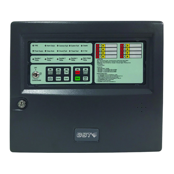
Relative humidity≤95%, non-condensing 1.3 Controls and Indications The fascia of the GST-116A is shown below in Fig. 1-1. There is no Control Enable 003 key-switch used on the large cabinet version panels as Access Level 2 is achieved when opening the front door (with glass window) which has a 003 lock. -
Page 12: Zone Status Indicators
GST102A/GST104A/GST108A/GST116A Conventional Fire Alarm Control Panel Installation and Operation Manual BATTERY FAULT: Yellow. It flashes when there is battery fault and illuminates steadily when the fault sound is silenced. CHARGER FAULT: Yellow. It flashes when there is charger fault and illuminates steadily after the fault sound is silenced. -
Page 13: Configuration And Functions
○ 3 Control board 4 Batteries 1.4.2 Configuration and Functions of GST-116A . GST-116A control panels have the following configuration and functions. Batteries: Standby power source for the CIE. Control board: For controlling power supply, charger, and all outputs such as fault/disable/supervisory relay output, alarm output, sounder outputs and repeater panel for zone 1 to 8, and monitoring the state of zone 1 to 8. -
Page 14: Configuration And Functions Of Gst-108A
Relay board (optional): Providing detection input and repeater output for zone 9 to 16. Controlling outputs of alarm relay and fault relay for zone 1 to 16. 1.4.3 Configuration and Functions of GST-108A GST-108A control panels have the following configuration and functions. Batteries: Standby power source for the CIE. -
Page 15: Terminals On Extension Board
GST102A/GST104A/GST108A/GST116A Conventional Fire Alarm Control Panel Installation and Operation Manual FAULT DIS./SUP ALARM SOUNDER OUTPUT NC COM NO NC COM NO REPEATER OUTPUT ZONE Z8 Z7 Z6 Z5 Z4 Z3 Z2 Z1 INPUT Fig. 1-4 FAULT (NC, COM, NO): Fault output terminal. -
Page 16: Terminals On Relay Board Of Rb116A
GST102A/GST104A/GST108A/GST116A Conventional Fire Alarm Control Panel Installation and Operation Manual Fig. 1-6 ZONE INPUT (9~16): Zone 9 to 16 input terminals. Z9~Z16: Output terminals of repeater panel for zone 9 to 16. 0V: Power supply negative terminal for repeater panel connection. - Page 17 GST102A/GST104A/GST108A/GST116A Conventional Fire Alarm Control Panel Installation and Operation Manual Fig. 1-9 FAULT1~FAULT8: Fault output terminals for zone 1 to 8. ALARM1~ALARM8: Alarm output terminals for zone 1 to 8. Page...
-
Page 18: Appearance And Dimensions
GST102A/GST104A/GST108A/GST116A Conventional Fire Alarm Control Panel Installation and Operation Manual 1.6 Appearance and Dimensions The appearance of control panel is shown in Fig. 1-10. Its dimensions are 430mm×98mm× 320mm (L×D×H). Fig. 1-10 Page... -
Page 19: Chapter 2 Installation And Wiring
GST102A/GST104A/GST108A/GST116A Conventional Fire Alarm Control Panel Installation and Operation Manual Chapter 2 Installation and Wiring 2.1 Installing the Cabinet The FACP is wall-mounted as in Fig 2-1A. Note: Cable connector should be installed in the knock-out hole to avoid cable abrasion and foreign objects. - Page 20 GST102A/GST104A/GST108A/GST116A Conventional Fire Alarm Control Panel Installation and Operation Manual Fig. 2-1B Page...
-
Page 21: Mains Connection
GST102A/GST104A/GST108A/GST116A Conventional Fire Alarm Control Panel Installation and Operation Manual 2.2 Mains Connection The CIE is powered by 220/230VAC. It’s recommended to use 1.5mm or above shield cable, subject to local installation codes. The incoming power cable ground (Green/Yellow) wire should be connected to terming G and be reliably grounded. -
Page 22: Zone Input Connection
GST102A/GST104A/GST108A/GST116A Conventional Fire Alarm Control Panel Installation and Operation Manual 2.4 Zone Input Connection Each zone can have maximum 32 fire detectors. The total number of detectors and call points in a zone should not exceed 32. They can be connected in two ways. -
Page 23: Chapter 3 System Setup
GST102A/GST104A/GST108A/GST116A Conventional Fire Alarm Control Panel Installation and Operation Manual Chapter 3 System Setup 3.1 Setting Access Levels The CIE provides three access levels: Level I, for anybody to silence the buzzer by pressing Mute/ACK key. Level II, for a fire warden or fire brigade personnel to disable, test, reset the panel, silence the buzzer, silence/resound the sounder outputs, evacuate the building and so on. -
Page 24: Disablement Of A Zone Or Output
GST102A/GST104A/GST108A/GST116A Conventional Fire Alarm Control Panel Installation and Operation Manual Table 3-5 Normally Normally open Output Voltage output closed contact contact Link pins DO NOT Link pins Link pins 1 & 2, 1 & 2, 2 & 3 CHANGE Alarm 4 &... -
Page 25: Operation Basic Steps - Generally Used For Individually Disabling Zones Or Sounder
GST102A/GST104A/GST108A/GST116A Conventional Fire Alarm Control Panel Installation and Operation Manual There are two ways for using disablement function: basic steps and quick disablement. ☆☆☆☆☆☆☆☆☆☆☆☆☆☆☆☆☆☆☆☆☆☆☆☆☆☆☆☆☆☆☆☆☆☆☆☆☆☆☆☆☆☆☆ Note: Disable status setting will be saved even if the CIE is powered off. ☆☆☆☆☆☆☆☆☆☆☆☆☆☆☆☆☆☆☆☆☆☆☆☆☆☆☆☆☆☆☆☆☆☆☆☆☆☆☆☆☆☆☆ 3.3.2 Operation Basic Steps – Generally used for individually Disabling Zones or Sounder /Alarm Outputs when the panel is in normal operation mode. -
Page 26: Setting Test Mode
GST102A/GST104A/GST108A/GST116A Conventional Fire Alarm Control Panel Installation and Operation Manual The following steps show how to operate the DISABLE button. Enter access level II as described in Section 3.1.2. First, pressing the SILENCE/RESOUND ALARM button silences the sounder output when any zone is in fire condition. -
Page 27: Test Zone Output Mode
GST102A/GST104A/GST108A/GST116A Conventional Fire Alarm Control Panel Installation and Operation Manual 3.4.3 Test zone output mode TEST ZONE OUTPUT MODE: When the “5” of SW3 (TEST ZONE OUT) is set to the ON position, test zone output mode is turned on. When a zone is in test mode and there is an alarm signal, coming from the zone, the sounder outputs associated to the zone will be automatically activated for 5 seconds. -
Page 28: Setting Associated Sounders To A Zone
GST102A/GST104A/GST108A/GST116A Conventional Fire Alarm Control Panel Installation and Operation Manual ☆☆☆☆☆☆☆☆☆☆☆☆☆☆☆☆☆☆☆☆☆☆☆☆☆☆☆☆☆☆☆☆☆☆☆☆☆☆☆☆☆☆ Note: If one of the outputs (sounder outputs or alarm output) is programmed with delay, then there should be at least one zone set as “With Manual Call Point” to ensure the delay could be overrode for immediate output. -
Page 29: Setting Delay Time Of Alarm Output
GST102A/GST104A/GST108A/GST116A Conventional Fire Alarm Control Panel Installation and Operation Manual 3.5.3 Setting Delay Time of Alarm Output Delay time of alarm output can be set through the following steps. Enter access level III. Set the “3” of SW2 (ALARM OUTPUT) to ON position. - Page 30 GST102A/GST104A/GST108A/GST116A Conventional Fire Alarm Control Panel Installation and Operation Manual Two sounder patterns are shown in Table 3-7. Default setting is Continuous Output Table 3-7 “5” of SW3 Sounder Patterns (SOUNDER MODE) Pulse Output Continuous Output OFF (Default) Delay time can be obtained as shown in Table 3-8. Default setting is 0 seconds Table 3-8 “1”...
-
Page 31: Supervisory Mode
GST102A/GST104A/GST108A/GST116A Conventional Fire Alarm Control Panel Installation and Operation Manual Supervisory Mode Use of Supervisory Function 3.6.1 Zones can be defined as supervisory for monitoring field device status. ☆☆☆☆☆☆☆☆☆☆☆☆☆☆☆☆☆☆☆☆☆☆☆☆☆☆☆☆☆☆☆☆☆☆☆☆☆☆☆☆☆☆☆ Note: Supervisory setting will be saved even if the CIE is powered off. -
Page 32: Setting Auxiliary Functions
GST102A/GST104A/GST108A/GST116A Conventional Fire Alarm Control Panel Installation and Operation Manual 3.7 Setting Auxiliary Functions RESOUND MODE: When the “6” of SW2 (RESOUND MODE) is set to the ON position, resound mode is turned on. When there is fire alarm from a zone, the sounder outputs associated to this zone will be started. -
Page 33: Restore Default Settings
GST102A/GST104A/GST108A/GST116A Conventional Fire Alarm Control Panel Installation and Operation Manual 3.10 Restore Default Settings The basic features of the default settings are as follows: Every zone is set “With Manual Call Point”. When there is fire alarm from any zone, all sounder outputs will be started, and these outputs will be continuous and not be delayed. -
Page 34: Chapter 4 Operation Instructions
GST102A/GST104A/GST108A/GST116A Conventional Fire Alarm Control Panel Installation and Operation Manual Chapter 4 Operation Instructions 4.1 Working State Description 4.1.1 State of Detection Zones Normal: If a zone is in normal condition, the zones’ red and amber LEDs are off, only the power LED (green) is on. -
Page 35: Description Of The Buzzer
GST102A/GST104A/GST108A/GST116A Conventional Fire Alarm Control Panel Installation and Operation Manual 4.1.5 Description of the Buzzer The buzzer of the CIE sounds by priority coming from high to low as follows: safe state, fire, supervisory, fault and normal. The sound patterns of the buzzer are: ... -
Page 36: Acknowledgement And Silence Of Fault
GST102A/GST104A/GST108A/GST116A Conventional Fire Alarm Control Panel Installation and Operation Manual 4.2 Acknowledgement and Silence of Fault A fault condition can be acknowledged and silenced from access level I. Pressing the SILENCE BUZZER button under a fault condition, the buzzer of the CIE will be silenced and the fault is acknowledged. -
Page 37: Chapter 5 Calculation Of Batteries Capacity
From the above, we can get the maximum battery capacity is 4.56AH, so that we recommended a 7AH battery to be used for the system. And as the above calculations are based on the 16-zone GST116A, they are also applicable to GST102A, GST104A and GST108A. Page... -
Page 38: Chapter 6 Servicing
GST102A/GST104A/GST108A/GST116A Conventional Fire Alarm Control Panel Installation and Operation Manual Chapter 6 Servicing The CIE shall be serviced by specially trained technicians. Please disconnect power before servicing. 6.1 Replacing the Batteries Type: Sealed lead-acid battery. Recommend period for replacement: 5 years(25℃)... -
Page 39: Troubleshooting
GST102A/GST104A/GST108A/GST116A Conventional Fire Alarm Control Panel Installation and Operation Manual 6.3 Troubleshooting Problem Possible Reason Resolution A. Check power connections A. Power not connected B. Replace the fuse F1. B. The F1 on control board is blown. C. Replace the control board. -
Page 40: Compliance Information
GST102A/GST104A/GST108A/GST116A Conventional Fire Alarm Control Panel Installation and Operation Manual Compliance information 2831-CPR-F4050 0832-UKCA-CPR- 548p/03 GST-0204-01 F0054 (Available for product models:GST-102A) 2831-CPR-F4051 0832-UKCA-CPR- 548p/04 GST-0204-01 F0055 (Available for product models:GST-104A) Page... -
Page 41: Weee Information
GST102A/GST104A/GST108A/GST116A Conventional Fire Alarm Control Panel Installation and Operation Manual 2831-CPR-F4049 0832-UKCA-CPR- 548p/05 GST-0204-01 F0056 (Available for product models:GST-108A) 2831-CPR-F4052 0832-UKCA-CPR- 548p/06 GST-0204-01 F0057 (Available for product models:GST-116A) WEEE Information 2012/19/EU (WEEE directive): Products marked with this symbol cannot be disposed of as unsorted municipal waste in the European Union. -
Page 42: Limited Warranty
Subject to applicable law, in no event shall the liability of GST and CRSS exceed the purchase price of the products. NO IMPLIED WARRANTY OF MERCHANTABILITY OR FITNESS FOR PARTICULAR PURPOSE SHALL APPLY. - Page 43 Gulf Security Technology Co., Ltd. No. 80 Changjiang East Road, ETDZ, Qinhuangdao, Hebei, P. R. China 066004 Tel: +86 (0) 335 8502434 service.gst@carrier.com www.gst.com.cn...
Need help?
Do you have a question about the GST102A and is the answer not in the manual?
Questions and answers