Advertisement
Quick Links
Advertisement

Related Manuals for GST GST301


Summary of Contents for GST GST301
-
Page 2: Table Of Contents
GST301 Extinguishing Control Panel Installation and Operation Manual CONTENTS General ........................ 1 Features ....................... 1 Technical Specifications ..................1 Structure and Operation Principle ................ 1 Mounting and Commission .................. 7 Operation ......................12 Troubleshooting ....................15 VIII Cautions ......................15... -
Page 3: I General
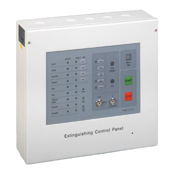
Installation and Operation Manual General GST301 Extinguishing Control Panel (hereinafter called the panel) is a stand-alone panel intended for use with gas extinguishing systems. The function of the panel is to monitor zones or areas for fire conditions and give an appropriate audible/visible indication. - Page 4 Primary STOP Sounder1 Fault tandby Sounder2 Batt Control Enable Fault Complies To EN 54-2 Fig. 1 Appearance Front panel Front panel of GST301 is shown in Fig. 2. FAULT/ISO ACTIVE Zone1 Silence Zone2 DELAY Reset TIME Aux Zone Release Lamp...
- Page 5 GST301 Extinguishing Control Panel Installation and Operation Manual Indicators Power Green. Lighted when power supplied. AC Fault Amber. Lighted when there is AC Fault. Batt Fault Amber. Lighted when battery voltage is below 5V. Gas Release Red.
- Page 6 GST301 Extinguishing Control Panel Installation and Operation Manual Pressure Switch FAULT Amber. Lighted by fault with pressure switch circuit. Extinguished when the fault is removed. Sounder 1 ACTIVE Green. Lighted when sounder 1 output is started. Extinguished when sounder 1 output is stopped.
- Page 7 GST301 Extinguishing Control Panel Installation and Operation Manual Fig. 3 Internal structure ⑴ AC transformer: 220/230VAC input, 27VAC output. ⑵ Input current fuse of the AC transformer: 1A ⑶ AC Input: 220/230VAC input ⑷ Main board ⑸ Battery: 12VDC 7Ah each ⑹...
- Page 8 GST301 Extinguishing Control Panel Installation and Operation Manual Fig. 4 Main board structure ⑴ X5: Discharge remote output mode setting (NO/NC) ⑵ X4: Fire remote output mode setting (NO/NC) ⑶ X6: Fault remote output mode setting (NO/NC) ⑷ X1: Sounder1 output mode setting (Active/NO/NC) ⑸...
-
Page 9: Mounting And Commission
GST301 Extinguishing Control Panel Installation and Operation Manual Fig. 5 Display board (1) X1: Emergency action mode setting by pin, with delay or without delay. (2) X2: Remote discharge remote output setting by pin, by pressure switch or output action. - Page 10 GST301 Extinguishing Control Panel Installation and Operation Manual Wire-in Hole Mounting Hole Fig. 6 Mounting Terminals BATT Aux Zone Zone Zone Sounder2 Sounder1 Standby Primary Aux+ Aux- Discharge Fire Fault Stage2 Fig. 7 Terminals (1) L, N: 220/230VAC input (2) PE: GND terminal (3) BATT+, -: Battery input connecting with internal or external battery.
- Page 11 GST301 Extinguishing Control Panel Installation and Operation Manual (8) Aux +, Aux -: Aux power supply (100mA/24VDC). (9) Standby +, - / Primary +, -: Gas release output connecting with primary and standby cylinder. 2A/24VDC active output can be set to NO/NC type. 2 to 45 seconds adjustable pulse output.
- Page 12 GST301 Extinguishing Control Panel Installation and Operation Manual Contact Output Panel 3kΩ 3kΩ Emergency Emergency Emergency Start/Abort Button Start/Abort Button Start/Abort Button Fig. 10 Wiring method of Emergency Start/Abort Button d) Wiring method when driving cylinder is of active output mode is shown in Fig.
- Page 13 GST301 Extinguishing Control Panel Installation and Operation Manual Fig. 13 Typical system connection Commission Configuring the outputs Defaults of sounder outputs and gas release output are at 24VDC Active type. To meet the condition on site, these outputs can be changed to normally-open or normally-closed dry contact output.
-
Page 14: Operation
GST301 Extinguishing Control Panel Installation and Operation Manual Configuring the Emergency Start Button Press the emergency start button in field can start the gas release with or without delay. Short X1 (on the display board) to set with delay and remove the jumper to set without delay. - Page 15 GST301 Extinguishing Control Panel Installation and Operation Manual Table 3 Cause Effect Sounder1 start immediately Zone1 alarm Fire remote output active immediately Sounder1 start immediately Zone2 alarm Fire remote output active immediately Sounder1 start immediately AUX Zone alarm ...
- Page 16 GST301 Extinguishing Control Panel Installation and Operation Manual Check the cables before connecting them to the panel. Ensure that there is no problem of short circuit, open circuit, earth fault and cross connection, etc. Note: If any zone, alarm circuit, or cylinder circuit is not used, an end of line resistor must be connected to the corresponding terminal.
-
Page 17: Troubleshooting
The panel itself is able to check and judge fault. If there is any short or broken circuit with wiring of a certain zone, the panel will light corresponding fault indicator, and output fault remote signal. If it still cannot work normally or still alarm fault, please contact GST technical support personnel. - Page 18 Gulf Security Technology Co., Ltd. No. 80, Changjiang East Road, QETDZ, Qinhuangdao, Hebei, P. R. China 066004 Tel: +86 (0) 335 8502434 Fax: +86 (0) 335 8502532 service.gst@fs.utc.com www.gst.com.cn...
Need help?
Do you have a question about the GST301 and is the answer not in the manual?
Questions and answers