Table of Contents
Advertisement
Quick Links
Advertisement
Table of Contents

Related Manuals for GST GST100


Summary of Contents for GST GST100
-
Page 2: Table Of Contents
GST100 Intelligent Fire Alarm Control Panel Installation and Operation Manual CONTENTS Chapter 1 Brief Introduction ....................1 Chapter 2 Technical Specifications ..................2 2.1 Operating Voltage ......................2 2.2 Standby Batteries ......................2 2.3 Detecting Loop Parameters....................2 2.4 Output Loop Parameters ....................2 2.5 RS485 Communication Loop .................... - Page 3 GST100 Intelligent Fire Alarm Control Panel Installation and Operation Manual 5.5 Fault Message ......................... 15 5.5.1 Fault Message Display ..................... 15 5.5.2 Disposal of Fault Message ..................16 5.6 Pre-alarm Message ......................16 5.6.1 Operation of Delay Mode ..................16 5.6.2 The First Stage......................
- Page 4 Chapter 8 Networking ......................36 8.1 General Description ......................36 8.2 Networking the FACP ...................... 36 8.2.1 Network of GST Series Panels ................. 36 8.2.2 Connecting with Repeater Panels ................36 8.3 Networking Method ......................36 8.3.1 GST Network ......................36 8.3.2 Connecting with Repeater Panels ................
-
Page 5: Chapter 1 Brief Introduction
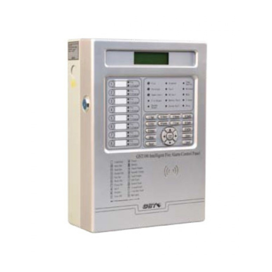
Installation and Operation Manual Chapter 1 Brief Introduction GST100 Intelligent Fire Alarm Control Panel is a mini- panel designed by EN54-2. It features simple installation, operation and maintenance, which make it ideal for smaller systems. Maximum 8 detection zones, each with independent fire LED, fault/disable LED and zone label. -
Page 6: Chapter 2 Technical Specifications
GST100 Intelligent Fire Alarm Control Panel Installation and Operation Manual Chapter 2 Technical Specifications 2.1 Operating Voltage +10% Input Voltage: 230V AC -15% Frequency: 50Hz Input Current: 0.2A Fuse: 2A Recommended Wiring: 1.5mm or above shield cable, complying with local installation code. -
Page 7: Rs485 Communication Loop
GST100 Intelligent Fire Alarm Control Panel Installation and Operation Manual Output Current: 0~500mA Terminal Resistor: 4.7K ALARM OUTPUT (NC,COM, NO) Contact Capacity: 24VDC @1.0A In case of a fire alarm or supervisory condition, NC and COM open, NO and COM close. -
Page 8: Chapter 3 Structure
GST100 Intelligent Fire Alarm Control Panel Installation and Operation Manual Chapter 3 Structure 3.1 Appearance and Internal Structure GST100 is wall-mounted. Its appearance, internal structure and connection are shown in Fig. 3-1 and Fig. 3-2. Knockout hole Fig. 3-1 LED Board... -
Page 9: Leds
GST100 Intelligent Fire Alarm Control Panel Installation and Operation Manual shown in Fig. 3-3. General LED Zonal LED Keypad Print Paper out Fig. 3-3 3.1.2 LEDs Colour Function How to clear General LED Fire Turns on when a fire alarm is... - Page 10 GST100 Intelligent Fire Alarm Control Panel Installation and Operation Manual OUTPUT Green sounder (R+, R-) outputs. panel is reset. ②Both LED illuminate when ② Both LED go off when the SOUNDER OUTPUT (R+, R-) is SOUNDER OUTPUT (R+, R-) disabled.
-
Page 11: Keys
GST100 Intelligent Fire Alarm Control Panel Installation and Operation Manual 3.1.3 Keys Function Changing the display among different windows when there are multiple messages. History Viewing the running records and fire alarm records. Browse Viewing detailed information of on-line loop devices, network panels and repeaters. -
Page 12: Optional Units
3.3.2 Manual Call Points A series of GST manual call point can be connected to the loop of GST100. When fire is confirmed manually, pressing the glass on the MCP, alarm signal can be sent to the FACP. After receiving the alarm signal, the FACP will show the number and location of the MCP, and sound alarm. -
Page 13: Chapter 4 Installation And Commission
GST100 Intelligent Fire Alarm Control Panel Installation and Operation Manual Chapter 4 Installation and Commission 4.1 Checking Please check the following items of the FACP before installation. Check project configuration Check the configuration according to packing list. The main items are: Installation and Operation Manual, and keys to the FACP, etc. -
Page 14: Connection Of Sounder Output Loop
EARTH: Terminal for checking ground fault, which is enabled by shorting it with a cable. A, B: RS485 loop output terminal for connecting GST network panels and repeater panels. 4.4.1 Connection of SOUNDER OUTPUT Loop The connection of SOUNDER OUTPUT loop is shown as Fig. -
Page 15: Loop Connection
GST100 Intelligent Fire Alarm Control Panel Installation and Operation Manual Diode Diode Terminal Sounder Sounder Resistor 4.7k Fig. 4-2 Description: Remove the terminal resistor. Connect the cable in correct polarization. Add a 4.7kΩ resister to the end of each loop. -
Page 16: Commission
GST100 Intelligent Fire Alarm Control Panel Installation and Operation Manual Max. 32 FACP Max. 64 repeater panels Fig. 4-4 4.5 Commission 4.5.1 Connection checking Check the loop conditions, measure the insulation resistance between the loop and ground, and inspect loop load, of which the insulation resistance should be more than 20MΩ , and loop load more than 1kΩ... -
Page 17: Chapter 5 Display And Disposal Of System Information
GST100 Intelligent Fire Alarm Control Panel Installation and Operation Manual Chapter 5 Display and Disposal of System Information The FACP can start operation after installed following instructions in Chapter 4. Turn on its power supply, it will start self-test and enter normal monitor status. It displays system normal screen if it works normally. -
Page 18: Rules For Sound Indication
Fig. 5-2 5.4 Fire Message 5.4.1 Fire Message Display GST100 control panel will generate alarm signal in 10 seconds when a detector alarms fire or a manual call point is pressed. (1) The LCD displays fire messages shown as Fig. 5-3. -
Page 19: Disposal Of Fire Message
GST100 Intelligent Fire Alarm Control Panel Installation and Operation Manual Last 043/043 2-023 Fire 15/12 13:26 Fire 001/043 2-031 15/12 13:26 Fig. 5-3 5.4.2 Disposal of Fire Message When fire alarm occurs, first find out the location according to the information shown on the FACP to verify if it’s a real fire. -
Page 20: Disposal Of Fault Message
GST100 Intelligent Fire Alarm Control Panel Installation and Operation Manual message type, and Fault and Maintenance LED illuminate. Fault 001/002 2-125 窗口 15/12 13:28 Dust 002/002 2-017 切换 15/12 13:50 Fig. 5-4 5.5.2 Disposal of Fault Message There are two types of fault in the system. One is control system fault such as AC or battery fault and loop fault;... -
Page 21: The First Stage
GST100 Intelligent Fire Alarm Control Panel Installation and Operation Manual 5.6.2 The First Stage (1) In delay mode, the FACP enters the first stage on receiving the first fire alarm signal. It will give fire alarm sound (fire truck sound). The LCD displays the message of that detector (zone, code and device type), and the delay time which decreases by second (Fig. -
Page 22: Action Message
GST100 Intelligent Fire Alarm Control Panel Installation and Operation Manual (2) The speaker gives supervisory sound (fire truck sound). The Supervisory LED illuminates. (3) The sounder of this zone and the common zone will be triggered. (4) If supervisory is enabled, the normally open contact of ALARM OUTPUT relay (NO, COM) is closed, and the normally closed contact (NC, COM) open, the Fire Output LED lights red. -
Page 23: Disable Messages
GST100 Intelligent Fire Alarm Control Panel Installation and Operation Manual Delay 001/002 2-115 Time:025 Delay 002/002 ----- Time:035 Fig. 5-9 The messages on the screen mean that there are 2 devices being delayed. The sounder number 115 in Zone 2 will activate after 25 seconds and SOUNDER OUTPUT (R+. R-) will activate after 35 seconds. -
Page 24: Chapter 6 Users' Guide
GST100 Intelligent Fire Alarm Control Panel Installation and Operation Manual Chapter 6 Users’ Guide 6.1 Rules for Menu Operation There are two methods to access the menu: (1) Pressing the corresponding number on the keypad. (2) Pressing the up and down key to highlight the menu item, and then press Enter. -
Page 25: Viewing Fire Messages
GST100 Intelligent Fire Alarm Control Panel Installation and Operation Manual Fire 001/043 2-031 15/12 10:15 Fault 002/043 2-023 15/12 13:26 Fig. 6-2 6.3.2 Viewing Fire Messages In the screen shown in Fig. 6-1, selecting “2.Fire History”, the system will enter the screen of viewing fire records. -
Page 26: Viewing Network Facp
GST100 Intelligent Fire Alarm Control Panel Installation and Operation Manual the device before or after it. In Fig. 6-5, we can see there are 98 devices on line and the current device No. 232 is in Zone 8 which is a manual call point. -
Page 27: Disabling / Enabling A Zone
GST100 Intelligent Fire Alarm Control Panel Installation and Operation Manual The first screen 1.Zone 2.Devices The second screen 3.Outputs 4.Pre-Alarm The third screen 5.Output Delays Fig. 6-8 Operations that can be disabled and enabled are: ⑴Zone: Disabling/enabling all devices of a zone. -
Page 28: Disabling / Enabling A Device
GST100 Intelligent Fire Alarm Control Panel Installation and Operation Manual (Disabled Sum) which is the total number of disabled zone will increase by 1. The zone number will also increase by 1 (if the disabled zone is zone 8, it changes to zone 1) as shown in Fig. -
Page 29: Disabling / Enabling Pre-Alarm
GST100 Intelligent Fire Alarm Control Panel Installation and Operation Manual (3) FAULT OUTPUT: There is a FAULT OUTPUT circuit and an LED for the FAULT OUTPUT. Selecting “3. Outputs” in the screen of Fig. 6-8 will enter the screen for setting the output status, as in Fig. -
Page 30: Disabling / Enabling Output Delay
GST100 Intelligent Fire Alarm Control Panel Installation and Operation Manual 6.5.5 Disabling / Enabling Output Delay If output delay is enabled, the control panel can delay the output of the sounders, ALARM OUTPUT (fire alarm output, supervisory output) and SOUNDER OUTPUT (R+, R-) (the FAULT OUTPUT cannot be delayed). -
Page 31: Time Setup
GST100 Intelligent Fire Alarm Control Panel Installation and Operation Manual (1) Disabled: No message will be printed out. (2) Print Fire: Only fire alarm messages will be printed out. (3) Print All: All messages will be printed out. Selecting “1. Printer Setup” in the screen of Fig. 6-8, will enter the screen for setting the printer as in Fig. -
Page 32: Delay Setup
GST100 Intelligent Fire Alarm Control Panel Installation and Operation Manual 6.6.3 Delay Setup Selecting “3. Delay Setup” in the screen of Fig. 6-8 will enter delay setup screen shown in Fig. 6-19. 1.Zone Delay 2.Common Delay Fig. 6-19 (1) Zone/STG 1: If pre-alarm is enabled, this is for setting the delay time of the first stage of pre-alarm. -
Page 33: Unlocking And Locking The Keypad
GST100 Intelligent Fire Alarm Control Panel Installation and Operation Manual The following functions can be realized by reset: (1) Clearing all current fire alarm and fault display; (2) Resetting the status indication LED of loop controlled fire suppression equipment. (3) Clearing the silenced status;... -
Page 34: Chapter 7 System Operator's Guide
GST100 Intelligent Fire Alarm Control Panel Installation and Operation Manual Chapter 7 System Operator’s Guide System configuration can be modified by pressing System (Fig. 7-1) where Level 2 password is required. The first screen 1.Definition 2.Register The second screen 3.Password 4.Device Modify... -
Page 35: Device Registration
GST100 Intelligent Fire Alarm Control Panel Installation and Operation Manual Code: Zone: Device Type: Fig. 7-2 You can input the device code after “Code”, and zone number after “Zone”, in which “0” stands for the common zone, and then input the device type. The icon of the device type will be displayed to avoid any possible mistake. -
Page 36: Password Setting
GST100 Intelligent Fire Alarm Control Panel Installation and Operation Manual Repeated! Please browse history! Fig. 7-4 Disposal of duplicated codes: (1) Press History and select “”All History” option; (2) The duplicated codes are shown as in Fig. 7-5, in which device No. 2 and 5 are duplicated. -
Page 37: Device Modification
GST100 Intelligent Fire Alarm Control Panel Installation and Operation Manual Press up and down key to select the item. After Enter is pressed, the system will enter the screen of password modification shown as Fig. 7-7. ****** Password: Confirm: ****** Fig. -
Page 38: Sensitivity Modification
GST100 Intelligent Fire Alarm Control Panel Installation and Operation Manual If the input code is beyond the available range or if the modification is unsuccessful, the screen will remain unchanged and waits to be modified. 7.5.2 Sensitivity Modification Selecting “2.Sense Modify” in the screen of Fig. 7-6, the system will enter the screen in Fig. - Page 39 GST100 Intelligent Fire Alarm Control Panel Installation and Operation Manual From the above figure we can see that digital device No. 162 is being monitored. The latest sampled value (temperature, smoke density and flame intensity) is 204. If the device is non-digital loop device, the screen will be as Fig. 7-15.
-
Page 40: Chapter 8 Networking
8.2 Networking the FACP 8.2.1 Network of GST Series Panels The loop terminal of network card of GST series panels can be connected to the RS-485 loop. The loop cable shall be 1.0mm or above twisted pair with total length not over 1Km. -
Page 41: Connecting With Repeater Panels
GST100 Intelligent Fire Alarm Control Panel Installation and Operation Manual 1.Display Setup 2.Address Setup Fig. 8-2 Local address Fig. 8-3 As different system requires different network function, the FACP is designed to be able to filter network information. In this mode, The FACP displays only its local messages, but does not display messages from other network panels. -
Page 42: Display Of Network Messages
GST100 Intelligent Fire Alarm Control Panel Installation and Operation Manual network card. There are four types of network fault which are network card fault, telephone line fault in case the remote monitoring network doesn’t work properly, network panel fault in case of the power down or off-normal communication with the network panels or repeater panels fault in case of power down with the repeater panels. -
Page 43: Chapter 9 Calculation Of Battery Capacity
GST100 Intelligent Fire Alarm Control Panel Installation and Operation Manual Chapter 9 Calculation of Battery Capacity Table 9-1 Current(A) Device Monitor Alarm FACP 0.1A 0.1A Loop Devices N×0.0008A N×0.002A Total Suppose I3 is the sum of SOUNDER OUTPUT and auxiliary output which is maximum 1A, Tj (H) is the monitor time, Ta (H) is the alarm time, and Tw (H) is the output time. -
Page 44: Chapter 10 Troubleshooting And Regular Inspection
GST100 Intelligent Fire Alarm Control Panel Installation and Operation Manual Chapter 10 Troubleshooting and Regular Inspection 10.1 Common Disposal Table 10-1 Problem Reason Solution No display or a. Abnormal power supply a. Check 230VAC power supply abnormal b. Loose connection with b. - Page 45 GST100 Intelligent Fire Alarm Control Panel Installation and Operation Manual Fig. 10-1 5) Turn on the power of the printer. Press SK1 key, feed the paper through by hand, the paper will enter slowly until it appears in front of the head. The scroll spindle has been replaced.
-
Page 46: Appendix 1 Internal Connection Diagram
GST100 Intelligent Fire Alarm Control Panel Installation and Operation Manual Appendix 1 Internal Connection Diagram Loop IN Loop OUT ALARM OUTPUT FAULT OUTPUT +24V NC NO COM NC EARTH Main Board Interface Board LED/Keypad Board BUSY To Battery Printer Speaker... -
Page 47: Appendix 2 Device Type List
GST100 Intelligent Fire Alarm Control Panel Installation and Operation Manual Appendix 2 Device Type List Device Type Action When Activity Undefined Smoke Detector Heat Detector Ultraviolet Flame Detector Fire Alarm Multi Detector Ultraviolet Flame Detector Infrared Beam Detector 51/52 Gas Detector... - Page 48 Gulf Security Technology Co., Ltd. No. 80, Changjiang East Road, QETDZ, Qinhuangdao, Hebei, P. R. China 066004 Tel: +86 (0) 335 8502434 Fax: +86 (0) 335 8502532 service.gst@fs.utc.com www.gst.com.cn...
Need help?
Do you have a question about the GST100 and is the answer not in the manual?
Questions and answers