Table of Contents
Advertisement
Quick Links
Advertisement
Table of Contents

Related Manuals for GST GST102A


Summary of Contents for GST GST102A
- Page 1 www.acornfiresecurity.com www.acornfiresecurity.com...
-
Page 2: Table Of Contents
1.5.3 Terminals on Signal Output Interface Board of GST116A ........10 1.5.4 Terminals on Signal Output Interface Board of GST108A ......... 11 1.5.5 Terminals on Signal Output Interface Board of GST102A/104A ....... 11 1.6 Dimensions ........................12 Chapter 2 Installation ......................13 2.1 Installing the Cabinet ....................... - Page 3 www.acornfiresecurity.com Installation and Operation Manual 2.4.1 Using end of line resistor ..................14 2.4.2 Using an Active End of Line Unit ................14 2.5 Sounder/Alarm Output Connection ................. 14 Chapter 3 System Setup ......................15 3.1 Setting Access Levels ...................... 15 3.1.1 Setting Access Level 1 ....................
- Page 4 Appendix 2 Wiring Diagram for GST108A FACP ..............30 Appendix 3 Wiring Diagram for GST104A FACP ..............31 Appendix 4 Wiring Diagram for GST102A FACP ..............32 Appendix 5 Appearance of GST116A FACP ................. 33 Appendix 6 Appearance of GST108A FACP ................. 33 Appendix 7 Appearance of GST104A FACP .................
-
Page 5: Installation Precautions
GST102A/104A/108A/116A Conventional Fire Alarm Control Panel Installation and Operation Manual Installation Precautions Adherence to the following will aid in problem-free installation with long-term reliability: Do not attempt to install, service, or operate this unit until this manual is read and understood. -
Page 6: 54 Information
GST102A/104A/108A/116A Conventional Fire Alarm Control Panel Installation and Operation Manual EN 54 Information GST102A/104A/108A/116A Conventional Fire Alarm Control Panel (FACP) complies EN 54 with the requirements of EN 54-2 1997 + A1: 2006 and EN 54-4 1997+A1: √ 2002+A2:2006. In addition to the basic requirements of these standards, the panel conforms to the following optional requirements. -
Page 7: Chapter 1 Product Overview
Chapter 1 Product Overview GST102A/104A/108A/116A Conventional Fire Alarm Control Panel is designed in compliance with EN 54-2. It’s compatible with GST C-9403 Conventional Sounder Strobe designed by EN 54-3, C-9103 Conventional Rate of Rise and Fixed Temperature Heat Detector by EN 54-5, C-9102 Conventional Photoelectric Smoke Detector by EN 54-7, and DC-9204 Conventional Manual Call Point by EN 54-11. -
Page 8: Batteries
Standby current of batteries when fully load: 0.1A Maximum operating current of the batteries: 2.5A Recommended Wiring (subject to local installation codes): GST fire cable Vencroft Gold and Platignum Nexans NX 200 and 200 Plus (LPCB tested) ... -
Page 9: Output Loop
GST102A/104A/108A/116A Conventional Fire Alarm Control Panel Installation and Operation Manual 1.2.6 Output Loop Recommended Wiring (subject to local installation codes): GST fire cable Vencroft Gold and Platignum Nexans NX 200 and 200 Plus (LPCB tested) ... -
Page 10: Common Status Indicators
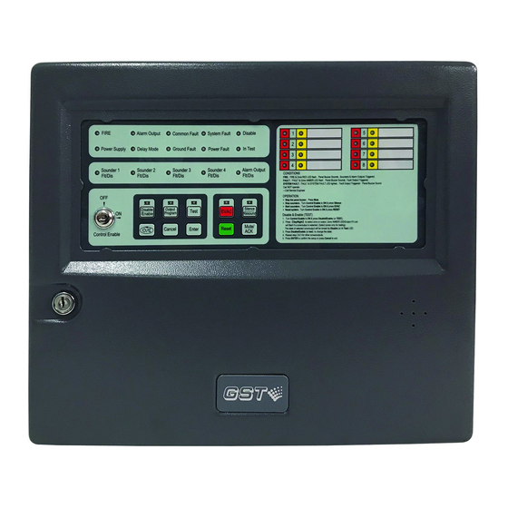
GST102A/104A/108A/116A Conventional Fire Alarm Control Panel Installation and Operation Manual 1.3.1 Common Status Indicators FIRE: It illuminates red steadily in fire condition. Alarm Output: It illuminates red steadily when the alarm output is activated. Common Fault: It flashes when the system enters a fault state and illuminates yellow steadily when the system enters safe state or Mute/ACK key is pressed. -
Page 11: Indicators Of Control Board
GST102A/104A/108A/116A Conventional Fire Alarm Control Panel Installation and Operation Manual illuminates steadily when Sounder 3 output is disabled. Sounder 4 Flt/Dis: Yellow. It flashes when Sounder 4 output is in fault condition, and it illuminates steadily when Sounder 4 output is disabled. -
Page 12: Configuration
GST102A/104A/108A/116A Conventional Fire Alarm Control Panel Installation and Operation Manual Fig. 1-3 1.4.2 Configuration The internal construction of the FACP is shown in Fig. 1-4. Fig. 1-4 ① Control board ② Extension board or signal output interface board ③ Display board ④... -
Page 13: Terminal Description
Batteries: In case mains power is cut, the FACP can automatically switch to batteries to provide power supply for uninterrupted operation. 1.4.2.4.2 Optional Configuration Signal output interface board is an optional part for GST102A which provides fire alarm output and fault output for Zone 1 to 2. 1.5 Terminal Description 1.5.1 Terminals on the Control Board... -
Page 14: Terminals On Gst116A Extension Board
GST102A/104A/108A/116A Conventional Fire Alarm Control Panel Installation and Operation Manual Fig. 1-5 REPEATER OUTPUT: Output terminal for repeater panel connection. PW ON: Power supply positive terminal for repeater panel connection. COM 0V: Power supply negative terminal for repeater panel connection. -
Page 15: Terminals On Signal Output Interface Board Of Gst108A
FAULT1~FAULT8: Fault output terminals for zone 1 to 8. ALARM1~ALARM8: Alarm output terminals for zone 1 to 8. 1.5.5 Terminals on Signal Output Interface Board of GST102A/104A The terminals on the signal output interface board GST102A/104A are similar to GST108A, only with fewer outputs connected. GST102A: ... -
Page 16: Dimensions
GST102A/104A/108A/116A Conventional Fire Alarm Control Panel Installation and Operation Manual ALARM1, ALARM2: Alarm output for Zone 1 and 2. GST104A: FAULT1~FAULT4: Fault output for Zone 1 to 4. ALARM1~ALARM4: Alarm output for Zone 1 to 4. -
Page 17: Chapter 2 Installation
GST102A/104A/108A/116A Conventional Fire Alarm Control Panel Installation and Operation Manual Chapter 2 Installation 2.1 Installing the Cabinet The FACP is wall-mounted as in Fig. 2-1. Note: Cable connector should be installed in the knock-out hole to avoid cable abrasion and foreign objects. -
Page 18: Zone Input Connection
GST102A/104A/108A/116A Conventional Fire Alarm Control Panel Installation and Operation Manual Note: Do not make battery connections until the installation is completed. The fuse of the batteries may be broken if the polarity is connected incorrectly. 2.4 Zone Input Connection Each zone can have maximum 15 fire detectors. -
Page 19: Chapter 3 System Setup
GST102A/104A/108A/116A Conventional Fire Alarm Control Panel Installation and Operation Manual Chapter 3 System Setup 3.1 Setting Access Levels The FACP provides three access levels: Level 1, for anybody to silence the buzzer by pressing Mute/ACK key. Level 2, for person on duty to disable, test, reset the panel, silence the sounders (using Silence/Resound key) and evacuate the building. -
Page 20: Setting Sounder/Alarm Output
GST102A/104A/108A/116A Conventional Fire Alarm Control Panel Installation and Operation Manual 3.2 Setting Sounder/Alarm Output 4 sounder outputs and 1 alarm output can be set through Pins (Pins X1, X2, X3, X4 and X5 is respectively corresponded to sounder output of zone 1 to 4 and alarm output ) on the control board to one of the three types including voltage output, normally open contact output or normally closed contact output. -
Page 21: Setting Test Mode
GST102A/104A/108A/116A Conventional Fire Alarm Control Panel Installation and Operation Manual will be turned off. Pressing key will switch the selected zone or output among Zone 1 to 8, Sounder outputs and Alarm Output. The amber LED for Zone 1 to 8 will flash when the zone is selected. Pressing Disable/Enable key can choose whether or not to disable the selected zone. -
Page 22: Setting The Facp To Default
GST102A/104A/108A/116A Conventional Fire Alarm Control Panel Installation and Operation Manual first set the system to Level 3 according to the instructions in Section 3.1.3. The FACP can be programmed through keypad for the functions below: Setting the system to default status;... -
Page 23: Setting Associated Sounders Of A Zone
GST102A/104A/108A/116A Conventional Fire Alarm Control Panel Installation and Operation Manual Manual Call Point”. 6 Press Enter to save the current settings and exit after all settings have been finished. The FACP will give 1s sound indication. Pressing Cancel will not save the setting. -
Page 24: Setting Delay Time Of Alarm Output
GST102A/104A/108A/116A Conventional Fire Alarm Control Panel Installation and Operation Manual Operation steps of zone association output setting are shown below. Enter Access Level 3 as described in Section 3.1.3. Set the “3” of SW2 (CFG Zonal output) on control board to ON position. -
Page 25: Setting Auxiliary Functions
GST102A/104A/108A/116A Conventional Fire Alarm Control Panel Installation and Operation Manual Flt/Dis LED flashes. “1” to “4” of SW3 are used for setting the delay time of Alarm Output (refer to Table 3-4). Pressing Enter to save the setting. The FACP will sound for 1s to indicate the successful setup. - Page 26 GST102A/104A/108A/116A Conventional Fire Alarm Control Panel Installation and Operation Manual Fig. 3-6 Page 22 www.acornfiresecurity.com...
-
Page 27: Chapter 4 Operation Instructions
GST102A/104A/108A/116A Conventional Fire Alarm Control Panel Installation and Operation Manual Chapter 4 Operation Instructions 4.1 Working State Description 4.1.1 State of Detection Zones Fire: If there is a zone in fire condition, FIRE LED and zone red LED flash (0.5s:0.5s). -
Page 28: Notes
GST102A/104A/108A/116A Conventional Fire Alarm Control Panel Installation and Operation Manual 4.1.6 Notes Access levels are downwards applicable. A higher level enables access at levels lower than it. If there is no key pressed for over 3 minutes or if the access level is changed, all previous operation will be canceled and the FACP would return to normal standby state. -
Page 29: Setting Day/Night Mode
GST102A/104A/108A/116A Conventional Fire Alarm Control Panel Installation and Operation Manual and carry out self-test. The self-test can check all indicators and the buzzer. All indicators illuminate and the buzzer sounds. After self-test, the panel returns to normal condition. If the RESET INPUT contact is shorted for over 2s, the FACP will start reset and self-test regardless of the current access level. -
Page 30: Chapter 5 Calculation Of Batteries Capacity
From the above, we can get the maximum battery capacity is 4.61AH, so that we recommended a 7AH battery to be used for the system. And as the above calculations are based on the 16-zone GST116A, they are also applicable to GST102A, GST104A and GST108A. Page 26... -
Page 31: Chapter 6 Servicing
GST102A/104A/108A/116A Conventional Fire Alarm Control Panel Installation and Operation Manual Chapter 6 Servicing The FACP shall be serviced by specially trained engineers. Please disconnect power before servicing. 6.1 Replacing the Batteries Type: Sealed lead-acid battery. Recommend period for replacement: 5 years(25℃)... - Page 32 GST102A/104A/108A/116A Conventional Fire Alarm Control Panel Installation and Operation Manual WEEE Information 2012/19/EU (WEEE directive): Products marked with this symbol cannot be disposed of as unsorted municipal waste in the European Union. For proper recycling, return this product to your local supplier upon the purchase of equivalent new equipment, or dispose of it at designated collection points.
-
Page 33: Appendix 1 Wiring Diagram For Gst116A Facp
GST102A/104A/108A/116A Conventional Fire Alarm Control Panel Installation and Operation Manual Appendix 1 Wiring Diagram for GST116A FACP Page 29 www.acornfiresecurity.com... -
Page 34: Appendix 2 Wiring Diagram For Gst108A Facp
GST102A/104A/108A/116A Conventional Fire Alarm Control Panel Installation and Operation Manual Appendix 2 Wiring Diagram for GST108A FACP Page 30 www.acornfiresecurity.com... -
Page 35: Appendix 3 Wiring Diagram For Gst104A Facp
GST102A/104A/108A/116A Conventional Fire Alarm Control Panel Installation and Operation Manual Appendix 3 Wiring Diagram for GST104A FACP Page 31 www.acornfiresecurity.com... -
Page 36: Appendix 4 Wiring Diagram For Gst102A Facp
GST102A/104A/108A/116A Conventional Fire Alarm Control Panel Installation and Operation Manual Appendix 4 Wiring Diagram for GST102A FACP Page 32 www.acornfiresecurity.com... -
Page 37: Appendix 5 Appearance Of Gst116A Facp
GST102A/104A/108A/116A Conventional Fire Alarm Control Panel Installation and Operation Manual Appendix 5 Appearance of GST116A FACP Appendix 6 Appearance of GST108A FACP Page 33 www.acornfiresecurity.com... -
Page 38: Appendix 7 Appearance Of Gst104A Facp
GST102A/104A/108A/116A Conventional Fire Alarm Control Panel Installation and Operation Manual Appendix 7 Appearance of GST104A FACP Appendix 8 Appearance of GST102A FACP Page 34 www.acornfiresecurity.com... - Page 39 www.acornfiresecurity.com www.acornfiresecurity.com...
Need help?
Do you have a question about the GST102A and is the answer not in the manual?
Questions and answers