Table of Contents
Advertisement
Advertisement
Table of Contents

Related Manuals for GST GST-M200


Summary of Contents for GST GST-M200
-
Page 2: Table Of Contents
GST-M200 Intelligent Fire Alarm Control Panel Installation and Operation Manual CONTENTS Fire Alarm System Limitations ..................1 Installation Precautions ....................3 1 Product Description ..................... 5 1.1 Features and Options ....................5 1.2 Technical Specifications ................... 6 1.3 Controls and Indicators .................... 8 1.3.1 LCD Display ...................... - Page 3 GST-M200 Intelligent Fire Alarm Control Panel Installation and Operation Manual 3.7 Walk Test (Maintenance Password) ............... 31 3.8 Configure Item (Maintenance Password) .............. 32 3.8.1 TIME / DATE ....................32 3.8.2 LCD Contrast ....................32 3.8.3 NAC Setup ...................... 33 4 Operating Instructions ....................
-
Page 4: Fire Alarm System Limitations
GST-M200 Intelligent Fire Alarm Control Panel Installation and Operation Manual Fire Alarm System Limitations While a fire alarm system may lower insurance rates, it is not a substitute for fire insurance! An automatic fire alarm system–typically made up of smoke detectors, heat detectors, manual pull stations, audible warning devices, and a fire alarm control with remote notification capability–can provide early warning of a developing fire. - Page 5 GST-M200 Intelligent Fire Alarm Control Panel Installation and Operation Manual Smoke detectors cannot be expected to provide adequate warning of fires caused by arson, children playing with matches (especially in bedrooms), smoking in bed, and violent explosions (caused by escaping gas, improper storage of flammable materials, etc.).
-
Page 6: Installation Precautions
GST-M200 Intelligent Fire Alarm Control Panel Installation and Operation Manual Installation Precautions Adherence to the following will aid in problem-free installation with long-term reliability: WARNING - Several different sources of power can be connected to the fire alarm control panel. Disconnect all sources of power before servicing. Control unit and associated equipment may be damaged by removing and/or inserting cards, modules, or interconnecting cables while the unit is energized. - Page 7 GST-M200 Intelligent Fire Alarm Control Panel Installation and Operation Manual It is imperative that the installer understands the requirements of the Authority Having Jurisdiction (AHJ) and be familiar with the standards set forth by the following regulatory agencies: Underwriters Laboratories Standards ...
-
Page 8: Product Description
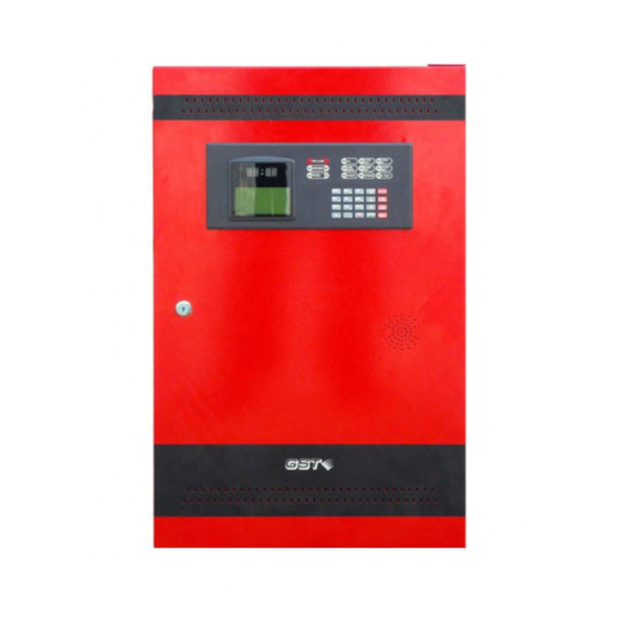
Installation and Operation Manual 1 Product Description GST-M200 Intelligent Fire Alarm Control Panel (FACP) complies to UL 864 standard with features of easy installation, operation, and maintenance. All circuit boards are installed in a metal cabinet, providing a complete fire control system for most applications. -
Page 9: Technical Specifications
GST-M200 Intelligent Fire Alarm Control Panel Installation and Operation Manual section 17AWG (1.0mm Compatible with GST’s series devices: DI-M9102/I-9102(UL) / JTY-GD-G3 Intelligent Photoelectric Smoke Detector DI-M9103/I-9103(UL) / JTW-ZCD-G3N Intelligent Rate of Rise and Fixed Temperature Heat Detector ... - Page 10 GST-M200 Intelligent Fire Alarm Control Panel Installation and Operation Manual which must comply with the actual supply power. When X2 is shorted, the FACP should work under 120VAC. When X2 is disconnected, the FACP should work under 220VAC. Battery (Sealed Lead Acid Only) - (BAT+, BAT-) ...
-
Page 11: Controls And Indicators
GST-M200 Intelligent Fire Alarm Control Panel Installation and Operation Manual XT10 0.75A max per circuit 1.2A max NAC1 per circuit Alarm 3.15A max per panel 1.2A max NAC2 per circuit Fig. 1-1 1.3 Controls and Indicators SYSTEM POWER FIRE ALARM... -
Page 12: Control And Indicating Part
GST-M200 Intelligent Fire Alarm Control Panel Installation and Operation Manual POWER ON: Green SUPERVISORY: Twin yellow LED ALARM SILENCE: Yellow GROUND FAULT: Yellow BATTERY FAULT: Yellow TROUBLE: Twin yellow LED DISABLED: Yellow ... -
Page 13: Components
GST-M200 Intelligent Fire Alarm Control Panel Installation and Operation Manual ALARM SILENCE key. Output can be silenced. The FACP will report fault when connected cable is in short or open circuit or ground fault. NAC2 (+, -): It outputs when there is fire alarm, which can be stopped by pressing ALARM SILENCE key. -
Page 14: Manual Pull Stations
In loop type fire alarm system, short circuit of part of the loop often affects normal operation of the whole system. GST-LD-8322 / C-9503 / C-M9503 Loop Isolator can disable the shorted part of loop from the whole system to ensure normal operation of other parts and can easily find the location of the disabled part. -
Page 15: Accessories
The handheld programmer has to be separately ordered. 1.8 Getting Started The following is a summary of the basic steps to bring a GST-M200 FACP on-line: Install the cabinet (refer to Section 2.1 Installing the Cabinet) ... - Page 16 GST-M200 Intelligent Fire Alarm Control Panel Installation and Operation Manual 113.5 Fig. 2-1 Dimensions for flush-mounting are shown in Fig. 2-2. Hole distance for flush-mounting: 640mm x 380mm x 113.5mm Page 13...
-
Page 17: Power
GST-M200 Intelligent Fire Alarm Control Panel Installation and Operation Manual 113.5 Fig. 2-2 2.2 Power WARNING: Several different sources of power can be connected to this panel. Disconnect all sources of power before servicing. The panel and associated equipment may be damaged by removing and/or inserting cards, modules or interconnecting cables while this unit is energized. -
Page 18: Battery Power
GST-M200 Intelligent Fire Alarm Control Panel Installation and Operation Manual Connector Note: Please make sure the mains power is in line with the rated voltage marked on the panel’s label. AC Power 120V/220V Fig. 2-3 Connect a wire from the grounding stud in the cabinet to a known solid earth ground in the building. -
Page 19: Notification Appliance Circuits (Nac)
GST-M200 Intelligent Fire Alarm Control Panel Installation and Operation Manual XT11 XT12 XT13 Alarm Fault Output Supervisory NC COM Relay contacts shown with power applied to panel and no active fault, alarm or supervisory. Fig. 2-5 2.5 Notification Appliance Circuits (NAC) There are two Style Y (Class B) NAC outputs on the loop interface board. -
Page 20: Signaling Line Circuits (Slc)
Fig. 2-7 Connection of SLC: C-9503 / C-M9503 / GST-LD-8322 Loop Isolator must be connected in SLC loop, each administrating a maximum of 30 addressable devices. The SLC can have at most 240 devices. Compatible devices are I-9102(UL) / JTY-GD-G3 Intelligent Photoelectric Smoke... -
Page 21: Programming
GST-M200 Intelligent Fire Alarm Control Panel Installation and Operation Manual Fig. 2-8 3 Programming 3.1 Programming Data Entry Totally 16 keys are provided: MODE 1; ABC 2; DEF 3; GHI 4; JKL 5; MNO 6; PQRS 7; *; + 0 ; 1st EVENT/TAB; ESC; △ = ; = ▽ ; ENTER. -
Page 22: Description Of Programming Screens
GST-M200 Intelligent Fire Alarm Control Panel Installation and Operation Manual In input mode, the cursor indicates the position. To input numbers, press the number keys directly. If “*” is to be used, press the “*” key. If more than one data section exists, the cursor goes to the next section after the present section is finished. -
Page 23: Programming (Master)
GST-M200 Intelligent Fire Alarm Control Panel Installation and Operation Manual messages, control panel functions, etc. Maintenance password is used by a qualified operator to access features such as Autoprogram, Disable/Enable, Walk test and Configure Item. 3.4 Programming (Master) Select “2. Programming” in the screen shown in Fig. 3-1, the system will request for password. - Page 24 ******** Fig. 3-4 Note: In the above example, “GST” is the contents of the banner. 3.4.1.2 Banner The contents of the banner are user-definable by selecting “2. Banner” in the screen of Fig. 3-3, the LCD will display the screen in Fig. 3-5.
- Page 25 GST-M200 Intelligent Fire Alarm Control Panel Installation and Operation Manual *Password Change* 1. Maintenance 2. Master Fig. 3-6 Modifying Maintenance Password Selecting “1. Maintenance” in the screen shown in Fig. 3-6 will cause the screen in Fig. 3-7 to appear for modifying maintenance password.
- Page 26 GST-M200 Intelligent Fire Alarm Control Panel Installation and Operation Manual for setting PAS delay time. * PAS Delay * RANGE 0-180 SECONDS Please Input: 000 Fig. 3-9 System default delay time is 000, which can be set from 0~180 seconds.
-
Page 27: Point Debug
GST-M200 Intelligent Fire Alarm Control Panel Installation and Operation Manual * My Words Setting * Please Input Words Number: 01 t[Detector Fig. 3-11 Here the user can define some commonly used phrases, which can then be used later when defining devices or entering other text to save programming time. To do this, the user needs to input the number of the text first, then the text itself (12 characters at most), like “Detector”... -
Page 28: Point Edit
GST-M200 Intelligent Fire Alarm Control Panel Installation and Operation Manual 3.4.3 Point Edit 3.4.3.1 Function The “Point Edit” option allows the operator to define the address, type, location, zone number of a device. With these information defined, the operator can quickly find the alarm zone and take timely measures in case of fire or trouble. - Page 29 GST-M200 Intelligent Fire Alarm Control Panel Installation and Operation Manual PAS. 2. Defining modules First enter the device code, press ENTER, the LCD indicates to input zone number. Input the zone number of the device. Pressing TAB to move the cursor to device type setting area for selecting device type (for example, SMOKE (ION), refer to Table 3-1).
-
Page 30: Event & Command
GST-M200 Intelligent Fire Alarm Control Panel Installation and Operation Manual @\xa Control Type @\xb Control Type @\xc Control Type Notification Appliance Circuit, can startup, Monitor Trouble PAS-Bypass PAS Disable @\xd PAS Disable FIRE-Relay FIRE ALARM output Relay Trouble Relay Trouble output Relay... - Page 31 GST-M200 Intelligent Fire Alarm Control Panel Installation and Operation Manual * Event & Command * 1.Edit E&C Delete E&C 2. Fig. 3-14 3.4.4.1 Meaning and Use of E&C Equation Use of E&C Equation An E&C consists of conditions, relation character and results.
- Page 32 GST-M200 Intelligent Fire Alarm Control Panel Installation and Operation Manual (including “*”) are entered. Changing of an existing “+” to “&” can be done by pressing + 0 and inputting “&”. Input of “+”: Press + 0 and input ”+”.
-
Page 33: Autoprogram (Master Password)
GST-M200 Intelligent Fire Alarm Control Panel Installation and Operation Manual 3.5 Autoprogram (Master Password) Select “3. Autoprogram” in the screen shown in Fig. 3-1, which is password protected. After entering master password, the system will register devices connected and networked, as in Fig. 3-17. -
Page 34: Walk Test (Maintenance Password)
GST-M200 Intelligent Fire Alarm Control Panel Installation and Operation Manual Disable Point Zone: 001 Code: 001 Type: 02 SMOKE (PHOTO) Fig. 3-19 Entering its zone number, code and type in sequence can disable a device. Selecting “2. Enable EQ”, disabled devices can be enabled, as in Fig. 3-20. -
Page 35: Configure Item (Maintenance Password)
GST-M200 Intelligent Fire Alarm Control Panel Installation and Operation Manual Entering number “2”, “Audible” is displayed to mean “Walk Test Audible” status. 3.8 Configure Item (Maintenance Password) Selecting “6. Configure Item” in the screen of Fig. 3-1, the system prompts for password. -
Page 36: Nac Setup
GST-M200 Intelligent Fire Alarm Control Panel Installation and Operation Manual LCD contrast can be changed by pressing the up and down key. 3.8.3 NAC Setup Selecting “3. NAC Setup” in the screen of Fig. 3-25 can set NAC1 and NAC2, as in the... -
Page 37: Operating Instructions
GST-M200 Intelligent Fire Alarm Control Panel Installation and Operation Manual 4 Operating Instructions 4.1 Panel Control Buttons 4.1.1 ACK/STEP (Maintenance Password) Pressing of ACK/STEP will acknowledge a new fire, fault, or supervisory event. Pressing ACK/STEP will result in the following actions. -
Page 38: Reset (Maintenance Password)
GST-M200 Intelligent Fire Alarm Control Panel Installation and Operation Manual 4.1.4 Reset (Maintenance Password) Pressing and releasing the Reset key, the following actions will be produced. Turning off all the NACs and control modules. Resetting all loop devices. -
Page 39: Trouble Operation
GST-M200 Intelligent Fire Alarm Control Panel Installation and Operation Manual appropriate section in this manual. Display contents of Banner 16/09-09 V*** SYSTEM ALL NORMAL Fig. 4-1 Description: The first line: Displaying the contents of Banner. The second line: Displaying current date by day-month-year order and software version of the FACP. -
Page 40: Alarm Operation
GST-M200 Intelligent Fire Alarm Control Panel Installation and Operation Manual will turn on the AC FAULT LED, a ground fault will turn on the GROUND FAULT LED, etc. For addressable devices connected to the SLC loop, the following is a typical message... -
Page 41: Waterflow Circuits Operation (For Future Use)
GST-M200 Intelligent Fire Alarm Control Panel Installation and Operation Manual ALARM 001 0f 040√ SMOKE (PHOTO) C001 16:34 0112 Z001 description: (32 char, 2 line) (40 char, 2 line) Fig. 4-3 Description: The first line: ALARM means alarm message. -
Page 42: Coded Operation
GST-M200 Intelligent Fire Alarm Control Panel Installation and Operation Manual ACTIVE SUPERVISORY 001 0f 040 C001 SUPERVISORY 16:34 0112 Z001 description: (32 char, 2line) Fig. 4-4 Description: The first line: “ACTIVE SUPERVISORY” means supervisory message. The second line: “001” is the number of the message and “040” is the number of total messages. -
Page 43: Walk Test
GST-M200 Intelligent Fire Alarm Control Panel Installation and Operation Manual of delay will start. The second period can be programmed up to 3 minutes. At the end of the second delay period, if fire alarm is not cleared, NACs will be activated. -
Page 44: System Point
GST-M200 Intelligent Fire Alarm Control Panel Installation and Operation Manual * History Record* No. 23 ALARM 16:23 23/03 Z001C001 SMOKE (PHOTO) Fig. 4-6 Description: The number and type of records can be displayed here, with their time, date, zone, device code and device type. -
Page 45: Disable Point
GST-M200 Intelligent Fire Alarm Control Panel Installation and Operation Manual Browse E&C Sum:003 ENTER E&C 01 E&C 02 E&C 03 Browse E&C 12343350&12332101+12341111&1234567 8=32150111 Fig. 4-8 4.11.4 Disable Point Selecting “5. Disable Point” in the screen of Fig. 4-5 can view information of disabled devices. -
Page 46: Default Programming
GST-M200 Intelligent Fire Alarm Control Panel Installation and Operation Manual P-9930 Ancillary device 1 x 0.05A=0.05A 1 x 0.05A =0.05A P-M9930 Modbus card 1 x0..05A =0.05A 1 x 0.1A = 0.05A P-M9960A network card 1 x 0.05A= 0.05A 1 x 0.11A =0.05A Loop isolator N x0.0015A =... -
Page 47: Wire Requirements
GST-M200 Intelligent Fire Alarm Control Panel Installation and Operation Manual 7 Wire Requirements WIRE REQUIREMENTS CIRCUIT CONNECTIONS Recommended Circuit Wire Type and Circuit Type Max. Distance Wire Gauge Function Limitations Feet (meters) Max. Distance is limited by the loop current. e.g. -
Page 48: Menu Operation Guide
GST-M200 Intelligent Fire Alarm Control Panel Installation and Operation Manual 8 Menu Operation Guide MODE 1. READ STATUS 1. VIEW HISTORY 2. SYSTEM POINT 3. EVENT&COMMAND 4. NETWORK FACP 5. DISABLE POINT 2 PROGRAMMING [Master Password Required] 1. POINT DEBUG 2. -
Page 49: Limited Warranty
GST-M200 Intelligent Fire Alarm Control Panel Installation and Operation Manual Limited Warranty The manufacturer warrants its products to be free from defects in materials and workmanship for 2 years from the date of manufacture, under normal use and service. Products are date-stamped at time of manufacture. The sole and exclusive obligation of the manufacturer is to repair or replace, at its option, free of charge for parts and labor, any part which is defective in materials or workmanship under normal use and service. -
Page 50: Appendix Basic System Connection
GST-M200 Intelligent Fire Alarm Control Panel Installation and Operation Manual Appendix Basic System Connection Notification Appliance Circuit (Power-limited Curcuit, Supervised) NAC #1 & NAC # 2 Style Y (Class B) 1.2A max 4.7K 4.7K SLC Loop (Power-limited Curcuits, Supervised) Style 6 (Class A) - Page 51 Gulf Security Technology Co., Ltd. No. 80, Changjiang East Road, QETDZ, Qinhuangdao, Hebei, P. R. China 066004 Tel: +86 (0) 335 8502434 Fax: +86 (0) 335 8502532 service.gst@fs.utc.com www.gst.com.cn...
Need help?
Do you have a question about the GST-M200 and is the answer not in the manual?
Questions and answers
on GST-M200 device LCD we have "SLC line1 fault ". Ho to solve this fault. Thanks a lot.
To resolve the "SLC line1 fault" on the GST-M200 device LCD, follow these steps:
1. Check Wiring: Ensure that the SLC loop wiring is intact and properly connected. Verify that power-limited and nonpower-limited wiring are separated as required.
2. Inspect Loop Isolators: Confirm that loop isolators are correctly installed and that no more than 30 addressable devices are connected per isolator.
3. Verify Device Connections: Ensure that all addressable devices are compatible (e.g., I-9102(UL), I-9103(UL), I-M9300, I-M9301) and properly addressed within the SLC loop.
4. Manually Reset the Fault: SLC line faults are latching and do not reset automatically. Perform a manual reset on the GST-M200 panel.
5. Check for Additional Faults: If the issue persists, look for additional trouble indicators, such as ground faults or AC power loss, and address them accordingly.
6. Review System Logs: Check the LCD for specific trouble messages, including device type, address, and fault description, to pinpoint the issue.
7. Test the System: Perform a self-test on all SLC devices to ensure proper operation.
Following these steps should help resolve the "SLC line1 fault."
This answer is automatically generated
@Mr. Anderson Thank you for your prompt answer. I did a lot all steps as you recommended including manual reset etc., prepare and check a simple circuit but without good results. Could you please check the attached pictures , may be you can advise more for me and what I can tried else. Thanks a lot. Waiting your soonest response. And one more additional question how I can set the factory (default) setting. Thanks again and best regards.
Net event setup explanation
The network event setup for the GST-M200 includes the following configurations:
1. NETWORK LOCAL ADDRESS
2. EVENT DISPLAY MODE
3. NETWORK FACP NAME
4. REPEATER NAME
These options allow for configuring network-related settings, event display preferences, and naming conventions for fire alarm control panels and repeaters.
This answer is automatically generated