Table of Contents
Advertisement
Quick Links
Advertisement
Table of Contents

Related Manuals for GST GST-IFP8


Summary of Contents for GST GST-IFP8
-
Page 2: Table Of Contents
GST-IFP8 Intelligent Fire Alarm Control Panel Installation and Operation Manual CONTENTS Installation Precautions ......................1 Preface EN 54 Information ....................2 Chapter 1 Product Introduction..................3 Chapter 2 Technical Specifications ...................1 2.1 Operating Voltage ......................1 2.2 Standby Batteries ......................1 2.3 Communication Loop Parameters ................1 2.3.1 RS485 Communication Loop ................1... - Page 3 GST-IFP8 Intelligent Fire Alarm Control Panel Installation and Operation Manual 4.5.2 Device Registration .................... 15 4.6 Device Definition ....................... 16 4.7 Field Device Commission..................16 Chapter 5 Display and Disposal of System Information ..........17 5.1 Normal Information ....................17 5.2 Fire Alarm ........................
-
Page 4: Installation Precautions
Consult with the appropriate Authority Having Jurisdiction (AHJ) for confirmation of specific requirements. GST-IFP8 Fire Alarm Control Panel (FACP) shall only be installed and serviced by trained specialists. Disconnect all sources of power before servicing. The control unit and associated equipment may be damaged by removing and/or inserting cards, modules, or interconnecting cables while the unit is energized. -
Page 5: Preface En 54 Information
GST-IFP8 Intelligent Fire Alarm Control Panel Installation and Operation Manual Preface EN 54 Information GST-IFP8 Intelligent Fire Alarm Control Panel (FACP) complies with the EN 54 requirements of EN 54-2 1997 + A1: 2006 and EN 54-4 1997 + A1: 2002 + √... -
Page 6: Chapter 1 Product Introduction
GST-IFP8 Intelligent Fire Alarm Control Panel Installation and Operation Manual Chapter 1 Product Introduction GST-IFP8 Intelligent Fire Alarm Control Panel (FACP) is designed to comply with EN 54-2 standard. With simple installation, operation, and easy maintenance, it is applicable in fire alarm system to have the following features: ... -
Page 7: Chapter 2 Technical Specifications
GST-IFP8 Intelligent Fire Alarm Control Panel Installation and Operation Manual Chapter 2 Technical Specifications 2.1 Operating Voltage Voltage: 220VAC/230VAC Frequency: 50Hz/60Hz Current: 1A Fuse: 2A delayed Recommended Wiring: 1.5mm or above screened cable, complying with local installation code. -
Page 8: Rs232 Communication Loop
FACP. NETWORK(loop type, even I+, I-, O+, O-) :Communication cable for connecting with up to 100 network FACPs from GST. ( I+ corresponds to CAN_L2, I- corresponds to CAN_H2, O+ corresponds to CAN_H1, O- corresponds to CAN_L1. CAN_H1 and CAN_L1 are to be connected with CAN_H2 and CAN_L2 of the next FACP;... -
Page 9: Detection Loop Parameters
GST-IFP8 Intelligent Fire Alarm Control Panel Installation and Operation Manual Nexans NX 200 and 200 Plus (LPCB tested) Prysmian FP 200 and 200 Gold Draka Firetuf and Firetuf Plus And all LPCB approved Fire cables Recommended Cable Length ≤3000m ... -
Page 10: Fault Output (Nc, Com, No)
GST-IFP8 Intelligent Fire Alarm Control Panel Installation and Operation Manual Output Current: 0mA~1000mA End of Line Resistor: 4.7kΩ 2.5.5 FAULT OUTPUT (NC, COM, NO) Contact Capacity: 24VDC @1.0A In fault state, NC and COM close, NO and COM open. -
Page 11: Chapter 3 Construction And Components
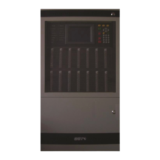
GST-IFP8 Intelligent Fire Alarm Control Panel Installation and Operation Manual Chapter 3 Construction and Components 3.1 Exterior and Interior Construction GST-IFP8 FACP is wall-mounted. Its exterior and interior construction are shown in Fig. 3-1 and 3-2. 191mm 484mm Fig. 3-1... -
Page 12: Display Area
GST-IFP8 Intelligent Fire Alarm Control Panel Installation and Operation Manual 3.1.1 Display Area The display area consists of LCD, LED indicators and keypad, which are shown in Fig. 3-3. Fig. 3-3 3.1.2 Description of LEDs Fire: Red. It illuminates when a connected detector to the FACP is in fire condition. -
Page 13: Description Of Keys
GST-IFP8 Intelligent Fire Alarm Control Panel Installation and Operation Manual Sounder Disable: Yellow. It illuminates when there is disabled loop sounder and goes out when the output is re-enabled. Disable: Yellow. It illuminates when any of the loop devices, OUTPUT TO FPE, OUTPUT TO SOUNDER or ALARM ROUTING OUTPUT is disabled. - Page 14 GST-IFP8 Intelligent Fire Alarm Control Panel Installation and Operation Manual Fig. 3-4 On the indication panel, each unit consists of two indicators and a label. The user can put the name of device on the right of the indicators. ...
-
Page 15: Zone Indication Panel
External Printer Card GST-IFP8 has an optional thermal Pinter inside. It also can connect with P-9904 Printer Interface Card for EPSON LQ-590K needle printer with USB less than 3m. Pre-alarm messages can be printed in real-time. -
Page 16: Periphery Devices
3.3.4 Manual Call Points A series of manual call point (such as I-9202) can be connected to the loop of GST-IFP8. When fire is confirmed manually, press the glass on the MCP, alarm signal can be sent to the FACP. After receiving the alarm signal, the FACP will show the number and location of the MCP, and sound alarm. -
Page 17: Sounder Strobes
FACP at the fire control center or by manual call points. A series of GST addressable sounder strobes (such as I-9403) can be connected to the loop of GST-IFP8. After activated, it will generate strong audible/ visual alarm signal. -
Page 18: Chapter 4 Installation
Please refer to Appendix 1 for the internal connection diagram. 4.2 Cabinet Installation GST-IFP8 FACP is flushed mounted. Dimensions of the cabinet are shown in Fig. 4-1. Ambient conditions for installation of the FACP: Temperature: 0℃~+40℃... -
Page 19: Start-Up Check
Check if the buzzer can give loud alarm sounds. 4.4 External Connection 4.4.1 Mains Connection GST-IFP8 Fire Alarm Control Panel receives power from a 220VAC/230VAC, 50Hz/60Hz supply. The incoming power feed cable Earth (Green/Yellow) wire should be connected to the earth terminal. -
Page 20: Battery Connection
Caution: Do not connect power to your device until you have completed all input and output connections. Failure to do so may result in injury! GST-IFP8 connects with field devices through mother board. Terminals on the mother board are shown in Fig. 4-3. - Page 21 GST-IFP8 Intelligent Fire Alarm Control Panel Installation and Operation Manual OUTPU FAULT LOOP1 LOOP2 LOOP3 LOOP4 LOOP5 LOOP6 LOOP7 LOOP8 LOOP9LOOP10 LOOP10 ALARM FEED OUTPUT TO REPEATER OUTPU SOUNDER ROUTING BACK O+ O- O+ O- O+ O- O+ O- O+ O-...
- Page 22 GST-IFP8 Intelligent Fire Alarm Control Panel Installation and Operation Manual connected cable is in short or open circuit. ALARM ROUTING: It outputs when there is fire alarm and gives fault signals when connecting line is shorted or opened. ...
- Page 23 GST-IFP8 Intelligent Fire Alarm Control Panel Installation and Operation Manual 4.4.3.3 Connection of ALARM ROUTING Connection of terminal ALARM ROUTING is shown in Fig. 4-6. Diode End of Line ALARM ROUTING Resistor 4.7kΩ Fire Monitoring Device Fire Monitoring Device End of Line...
- Page 24 GST-IFP8 Intelligent Fire Alarm Control Panel Installation and Operation Manual 4.4.3.5 Connection of Communication Loop Non-ring network is connected as shown in Fig. 4-8a. 控制器 控制器 控制器 控制器 FACP FACP FACP FACP Network Network Any Loop 最多可连接240台控制器 Maximum 240 FACPs 任一回路...
-
Page 25: Connection Inspection And Device Registration
GST-IFP8 Intelligent Fire Alarm Control Panel Installation and Operation Manual Monitor and control network is connected shown in Fig.4-8d through P-9935 Modbus Communication Card. Fig.4-8d Repeater loop connection is shown in Fig. 4-8e. Maximum 64 repeater panels Repeater Fig. 4-8e 4.5 Connection Inspection and Device Registration... -
Page 26: Device Definition
GST-IFP8 Intelligent Fire Alarm Control Panel Installation and Operation Manual Fig. 4-9 Step 2: Reboot the FACP while it’s in commission state. The FACP will automatically register devices. Please check the number, address and working state of the registered devices in according to engineering requirement, and remove any problem. -
Page 27: Chapter 5 Display And Disposal Of System Information
Installation and Operation Manual Chapter 5 Display and Disposal of System Information GST-IFP8 can be started after installation according to description in Chapter 4. Turn on the power supply, and main and standby power switch on the FACP, the FACP executes self-test and enter normal standby state. -
Page 28: Fire Alarm
GST-IFP8 Intelligent Fire Alarm Control Panel Installation and Operation Manual 5.2 Fire Alarm 5.2.1 Fire Alarm Indication Fire LED is lit when there is fire alarm signal. The buzzer of the FACP sounds (continuous sound), and corresponding fire LED on the zone indication panel is also lit. -
Page 29: Pre-Alarm
GST-IFP8 Intelligent Fire Alarm Control Panel Installation and Operation Manual Step 2: Press EVAC or F1 and F2 to evacuate the people in field. Step 3: Call the fire department. Step 4: Initiate extinguishers. If it is a false alarm, please take the following measures. -
Page 30: Disposal Of Pre-Alarm
GST-IFP8 Intelligent Fire Alarm Control Panel Installation and Operation Manual 5.3.2 Disposal of Pre-alarm The FACP provides two types of dependency on more than one alarm signal in zone setup. If a zone is set as Type A dependency, the alarm of a detector from this zone will be reported as a pre-alarm, and only when there is another detector from the same zone alarms, will the FACP report a fire alarm. - Page 31 GST-IFP8 Intelligent Fire Alarm Control Panel Installation and Operation Manual The panel generates fault sound. Fault relay outputs. Battery fault: The panel will reports battery fault if the battery voltage is lower than 21VDC or the internal resistance is higher than 0.7 ohm, and: ...
-
Page 32: Disposal Of Fault Message
GST-IFP8 Intelligent Fire Alarm Control Panel Installation and Operation Manual 5.6.2 Disposal of Fault Message There are two kinds of fault message. One is system fault, like mains fault, battery fault, and loop fault. The other is field device fault, like fault with detectors and modules etc. -
Page 33: Chapter 6 Description Of System Operation
GST-IFP8 Intelligent Fire Alarm Control Panel Installation and Operation Manual Chapter 6 Description of System Operation 6.1 Keypad 6.1.1 Keypad Functions Keys fall into different types by function: numerical keys, special functional keys, and direction control keys. Numerical keys are used for entering numbers and characters. -
Page 34: User Operation Instruction (Operator Password Required)
GST-IFP8 Intelligent Fire Alarm Control Panel Installation and Operation Manual 6.2 User Operation Instruction (Operator Password Required) Pressing USER SETUP in normal standby state and entering operator password will enter user setup menu. Operator Please input password password ******** Supv.:000... - Page 35 GST-IFP8 Intelligent Fire Alarm Control Panel Installation and Operation Manual 6.2.1.1 Browsing Devices Choosing 1 on the screen shown in Fig. 6-2 will enter the screen for browsing devices, as in Fig. 6-3. CARD SUM:01 LOOP SUM:02 DEVICE SUM:0484 ENTER...
- Page 36 GST-IFP8 Intelligent Fire Alarm Control Panel Installation and Operation Manual ZONE SUM:041 DEVICE SUM:484 ENTER ******************************************* Zone:001 Devices sum:0030 Led:001 Building 001 Zone:002 Devices sum:0030 Led:002 Building 002 Zone No:001 Device sum:0030 Zone:003 Devices sum:0030 Led:003 ******************************************* Building 003 D001 Zone-001 Loop-02 HEAT DETECTOR...
- Page 37 GST-IFP8 Intelligent Fire Alarm Control Panel Installation and Operation Manual 6.2.1.4 Browsing Duplicated Addresses Choosing 4 on the screen shown in Fig. 6-2 will enter the screen for browsing duplicated addresses, as in Fig. 6-6. Fig. 6-6 6.2.1.5 Browsing FACP Status Choosing 5 on the screen shown in Fig.
- Page 38 GST-IFP8 Intelligent Fire Alarm Control Panel Installation and Operation Manual *BROWSE C&E EQUATIONS* ******************************************* C&E EQUATIONS total num:001 No.001 10100102+10100302× 10100302= 0000006499 0000006599 0000006699 ->Press [F1] to print All Equations FAR:OK FPE:DIS OTS:OK 20:44:30 Fig. 6-8 The part before “=” is the condition and that after it is the result.
-
Page 39: System Time Setup
GST-IFP8 Intelligent Fire Alarm Control Panel Installation and Operation Manual *HISTORY LOG* ******************************************* 1.FIRE HISTORY 2.COMMON HISTORY 3.INITIALIZATION FAR:OK FPE:DIS OTS:OK 20:44:30 Fig. 6-9 The log of fire alarm, common history information and initialization can be browsed under this menu. If the printer is set in “All History” mode, the log can be printed out by choosing ENTER during browsing. -
Page 40: Printer Setup
GST-IFP8 Intelligent Fire Alarm Control Panel Installation and Operation Manual 6.2.3 Printer Setup Choosing 3 on the screen shown in Fig. 6-1 will enter the screen for printer setup, as in Fig. 6-11. On this screen, “1” means printing is disabled, “2” means only fire alarm messages are to be printed, and “3”... -
Page 41: Fire Alarm Acknowledgement Timer
GST-IFP8 Intelligent Fire Alarm Control Panel Installation and Operation Manual Choosing “2. Enable”, delay output of all output-type devices is allowed, and the FACP enters day mode or night mode according to the pre-set start/stop time. If, when the FACP works in day mode, alarm dependency Type A or Type B is set and the condition for dependency is not met within the pre-alarm delay period, the pre-alarm will automatically change to fire alarm. - Page 42 GST-IFP8 Intelligent Fire Alarm Control Panel Installation and Operation Manual Choosing “1” in the above screen will test all LED indicators and the buzzer. Choosing “2” will test all output ports of the FACP, which are OUTPUT TO SOUNDER, OUTPUT TO FPE, and ALARM ROUTING as shown in Fig.
-
Page 43: Start/Stop
GST-IFP8 Intelligent Fire Alarm Control Panel Installation and Operation Manual Choosing “4” in the screen of Fig. 6-14 can cancel the testing mode of one zone or all zones. After the testing mode is cancelled, the fire alarm message from the zone will be automatically cleared. -
Page 44: Instructions For System Administrator (Manager Password Required)
GST-IFP8 Intelligent Fire Alarm Control Panel Installation and Operation Manual *DISABLE/ENABLE* ******************************************* 1.DIS/ENABLE DEVICE-BY CODE 2.DIS/ENABLE DEVICE-BY ADDRESS 3.DIS/ENABLE ZONE 4.DIS/ENABLE SOUNDER FAR:OK FPE:DIS OTS:OK 20:44:30 Fig. 6-18 Choosing “1” on the screen in Fig. 6-18 enter the screen for disabling or enabling devices. -
Page 45: System Resource Setup
GST-IFP8 Intelligent Fire Alarm Control Panel Installation and Operation Manual Manager password Please input password ******** FAR:OK FPE:DIS OTS:OK 20:44:30 Fig. 6-20 6.3.1 System Resource Setup Choosing “1” on the screen of Fig. 6-20, the FACP enters the menu for setting up system resources, as in Fig. - Page 46 GST-IFP8 Intelligent Fire Alarm Control Panel Installation and Operation Manual 6.3.1.1 Device Setup Choosing “1” on the screen of Fig. 6-21 will enter the screen for setting up devices. Device address Loop *DEVICE SETUP* number Loop:01 Address(1-242):001 ******************************************* FAR:OK FPE:DIS OTS:OK 20:44:30 Fig.
- Page 47 GST-IFP8 Intelligent Fire Alarm Control Panel Installation and Operation Manual 6.3.1.2 Zone Setup Choosing “2” on the screen of Fig. 6-21 will enter the screen for setting up zones. *ZONE SETUP* Zone No. ENTER Zone(1-999):001 ******************************************* *ZONE SETUP* Zone(1-999):001 *******************************************...
- Page 48 GST-IFP8 Intelligent Fire Alarm Control Panel Installation and Operation Manual 6.3.1.3 Communication Setup Choosing “3” on the screen of Fig. 6-21 will enter the screen for communication setup. Monitoring devices and network devices in the system can be connected with the FACP using the sub-menus under this screen.
- Page 49 GST-IFP8 Intelligent Fire Alarm Control Panel Installation and Operation Manual 6.3.1.5 Password Modification Choosing “5” on the screen of Fig. 6-21 will enter the screen for password modification. Fig. 6-27 Operator password is used to access USER SETUP, and manager password for SYSTEM SETUP.
- Page 50 GST-IFP8 Intelligent Fire Alarm Control Panel Installation and Operation Manual automatically carry out the command of “immediate start” or “delay start” on devices being controlled according to these logical expressions. The Cause and Effect equations in this system consist of two parts linked by an equal mark. The part before...
- Page 51 GST-IFP8 Intelligent Fire Alarm Control Panel Installation and Operation Manual to check the grammar of C&E equations, which means that illegal characters will not be accepted. 6.3.1.6.3 Modifying C&E Equations Choosing “2” in the screen of Fig. 6-28 will enter the screen for modifying C&E equations.
-
Page 52: Local Output Setup
GST-IFP8 Intelligent Fire Alarm Control Panel Installation and Operation Manual *LOCAL OUTPUT SETUP* ******************************************* SOUNDERA mode(0-2):0-on one fire F.P.E.A mode(0-2):0-on one fire ALARM ROUTINGA mode(0-2):0-on one fire DELAY TIME:[ ] *10SEC-IN DELAY MODE FAR:OK FPE:DIS OTS:OK 20:44:30 Fig. 6-30 Output mode options 0 to 2: ... -
Page 53: Commissioning
GST-IFP8 Intelligent Fire Alarm Control Panel Installation and Operation Manual 6.3.4 Commissioning Choosing “4” in the screen of Fig. 6-20 will enter the menu for commissioning. Fig. 6-32 Choosing “1” in the above screen can register all loop devices. Choosing “2” can check loop devices with duplicated addresses, and find out if the detector device types are in compliance with originally defined. - Page 54 GST-IFP8 Intelligent Fire Alarm Control Panel Installation and Operation Manual Choose “5” on the screen of Fig. 6-32 for commissioning in analog mode, as in Fig. 6-34. Fig. 6-34 Choose “6” on the screen of Fig. 6-32 for commission in digital mode, as in Fig. 6-35.
-
Page 55: Chapter 7 Standby Battery Calculations
GST-IFP8 Intelligent Fire Alarm Control Panel Installation and Operation Manual Chapter 7 Standby Battery Calculations Equation for calculating the battery capacity: Battery capacity(Ah)=I ×T ) ×T Qmax Qmin Lmax Fout In which: =1.4A, which is the quiescent current when the FACP is full-loaded;... -
Page 56: Chapter 8 Maintenance
GST-IFP8 Intelligent Fire Alarm Control Panel Installation and Operation Manual Chapter 8 Maintenance The FACP shall only be repaired by specially trained GST technical service personnel. Please disconnect the power before repair! Warning: The key to the FACP shall be kept by specially assigned maintenance personnel! 8.1 Replacing the Battery... -
Page 57: Appendix 1 Internal Connection Diagram
GST-IFP8 Intelligent Fire Alarm Control Panel Installation and Operation Manual Appendix 1 Internal Connection Diagram G 5V TX RX XT15 XT20 TX RX V+ V- Cabinet Lining Board Earth Stud Earth Stud Keypad Board LED Board Switch Board Mother Board... -
Page 58: Appendix 2 Internal Fault Description
GST-IFP8 Intelligent Fire Alarm Control Panel Installation and Operation Manual Appendix 2 Internal Fault Description Problems Description Causes AC Power AC power fault No AC power Battery Battery fault No battery or low voltage BAT Resistance Battery high resistance Battery aging or loose connection. -
Page 59: Appendix 3 Device Type List
GST-IFP8 Intelligent Fire Alarm Control Panel Installation and Operation Manual Appendix 3 Device Type List Device Type Group Device Type UNDEFINED Undefined MULTISENSOR HEAT DETECTOR OPTICAL SMOKE USER DEFINED GAS DETECTOR BEAM DETECTOR Fire Alarm Signal Input Devices FLAME DETECTOR... - Page 60 GST-IFP8 Intelligent Fire Alarm Control Panel Installation and Operation Manual PRESSURE SWITCH USER DEFINED USER DEFINED USER DEFINED USER DEFINED USER DEFINED USER DEFINED USER DEFINED USER DEFINED USER DEFINED USER DEFINED USER DEFINED NET SounderA USER DEFINED USER DEFINED...
- Page 61 GST-IFP8 Intelligent Fire Alarm Control Panel Installation and Operation Manual Undefine Undefine Undefine Undefine Undefine Undefine Undefine Undefine Undefine Undefine Undefine Page 51...
-
Page 62: Appendix 4 Operation Menu
GST-IFP8 Intelligent Fire Alarm Control Panel Installation and Operation Manual Appendix 4 Operation Menu User Setup BROWSE BROWSE DEVICES BROWSE ZONES BROWSE GROUPS BROWSE DEPLICATED ADDRESS BROWSE PANEL STATUS BROWSE C&E EQUATIONS BROWSE LOG CLOCK PRINTER SETUP DISABLE Only Fire... - Page 63 GST-IFP8 Intelligent Fire Alarm Control Panel Installation and Operation Manual System setup PROGRAMMING DEVICE SETUP ZONE SETUP COMMUNICATION SETUP DAY/NIGHT TIME SETUP MODIFY PASSWORD C&E EQUATION SETUP DEVICE TYPE SETUP LOCAL OUTPUT SETUP WORKING STATE SETUP COMMISSION MONITORING COMMISSIONING DEVICE LEARN...
-
Page 64: Appendix 5: Index Of Information Required By En54-2
GST-IFP8 Intelligent Fire Alarm Control Panel Installation and Operation Manual Appendix 5: Index of Information Required by EN54-2 Chapters or sections EN54-2 Clause 12.2 in this manual General description of the equipment Chapter 1 Optional functions with requirements of EN54-2, 12.2.1.a... -
Page 65: Appendix 6: Compliance Information
GST-0204-01 (Available for product models:GST-IFP8,GST-IFP8-PT,GST-IFP8-HU) 2831-CPR-F0994 GST-0204-01 (Available for product models:GST-IFP8-SP, GST-IFP8-IT, GST-IFP8-FR, GST-IFP8-TK) WEEE Information 2012/19/EU (WEEE directive): Products marked with this symbol cannot be disposed of as unsorted municipal waste in the European Union. For proper recycling, return this product to your local supplier upon the purchase of equivalent new equipment, or dispose of it at designated collection points. - Page 66 Gulf Security Technology Co., Ltd. No. 80, Changjiang East Road, QETDZ, Qinhuangdao, Hebei, P. R. China 066004 Tel: +86 (0) 335 8502434 Fax: +86 (0) 335 8502532 service.gst@fs.utc.com www.gst.com.cn...
Need help?
Do you have a question about the GST-IFP8 and is the answer not in the manual?
Questions and answers