Table of Contents
Advertisement
Quick Links
Instruction Manual
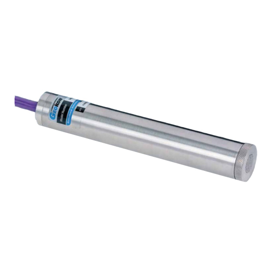
Model 3400 series
Semiconductor Piezometer
No part of this instruction manual may be reproduced, by any means, without the written consent of Geokon, Inc.
The information contained herein is believed to be accurate and reliable. However, Geokon, Inc. assumes no responsibility for
errors, omissions, or misinterpretation. The information herein is subject to change without notification.
Copyright © 1983-2018 by Geokon, Inc.
(REV H, 02/12/2018)
Advertisement
Table of Contents

Subscribe to Our Youtube Channel
Related Manuals for Geokon 3400 Series


Summary of Contents for Geokon 3400 Series
- Page 1 Model 3400 series Semiconductor Piezometer No part of this instruction manual may be reproduced, by any means, without the written consent of Geokon, Inc. The information contained herein is believed to be accurate and reliable. However, Geokon, Inc. assumes no responsibility for errors, omissions, or misinterpretation.
- Page 3 Upon examination by Geokon, if the unit is found to be defective, it will be repaired or replaced at no charge. However, the WARRANTY is VOID if the unit shows evidence of having been tampered with...
-
Page 5: Table Of Contents
TABLE of CONTENTS 1. THEORY OF OPERATION ..........................1 2. PRELIMINARY TESTS ............................2 3. SATURATING FILTER TIPS ..........................3 3.1 S ..................3 ATURATING NTRY TANDARD ILTERS 3.2 S ....................3 ATURATING NTRY ERAMIC ILTERS 3.2.1 One Bar Filters ............................. 3 3.2.2 Two Bar and Higher Filters ......................... - Page 6 FIGURES 1 - M 3400 P ......................1 IGURE ODEL IEZOMETER SSEMBLY 2 - T ......................6 IGURE YPICAL OREHOLE NSTALLATIONS 3 - H ..........................8 IGURE NTRY ILTER 4 - L ONLY......................... 8 IGURE NTRY ILTERS 5 - T ......................
-
Page 7: Theory Of Operation
1. THEORY OF OPERATION Geokon Model 3400 Piezometers are intended for dynamic measurements of fluid and/or pore water pressures in standpipes, boreholes, embankments, pipelines, pressure vessels, reservoirs, etc. They are also used for static pressure movement where the readout system is incompatible with vibrating wire type transducers. -
Page 8: Preliminary Tests
2. PRELIMINARY TESTS • Upon receipt of the piezometer, connect it to the readout using the wiring charts shown in Appendix C, and check that the zero pressure reading is within 1% F.S. of the value shown on the calibration report after due correction for barometric pressure, elevation above sea level and temperature. -
Page 9: Saturating Filter Tips
Salts in the water can be deposited into the filter stone causing it to become clogged if it is allowed to dry out completely. Filter stones may be replaced with screens for standpipe installations. Screens available from Geokon are less likely than standard filters to collect salt and become clogged. -
Page 10: Two Bar And Higher Filters
3.2.2 Two Bar and Higher Filters The proper procedure for de-airing and saturating these filters is somewhat complex; therefore, it is recommended that saturation be done at the factory by Geokon. If saturation must be done in the field, carefully follow the instructions below: 1) Place the assembled piezometer, filter down, in a vacuum chamber that has an inlet port at the bottom for de-aired water. -
Page 11: Installation
3) Allow 15 to 20 minutes for the temperature to stabilize before taking the reading. 4.2 Installation in Boreholes Geokon piezometers can be installed in cased or uncased boreholes, in either single or multiple piezometer configurations. If pore pressures in a particular zone are to be monitored, careful attention must be paid to the borehole sealing technique. -
Page 12: Figure 2 - Typical Borehole
Installation B: The borehole is filled from the “collection zone” upwards with an impermeable bentonite grout. (See Figure 2.) Figure 2 - Typical Borehole Installations Installation C: It should be noted that since the piezometer is essentially a no flow instrument, collection zones of appreciable size are not required. -
Page 13: Installation In Fills And Embankments
Green, FMGM proceedings Oslo 2003. Copies are available from Geokon. 4.3 Installation in Fills and Embankments Geokon piezometers are normally supplied with direct burial cable suitable for placement in fills such as highway embankments and dams, both in the core and in the surrounding materials. -
Page 14: Figure 3 - High Air Entryf
Figure 3 - High Air Entry Filter In partially saturated fills (if only the pore air pressure is to be measured,) the standard tip is satisfactory. It should be noted that the standard coarse tip (low air entry) measures the air pressure when there is a difference between the pore air pressure and the pore water pressure. -
Page 15: Installation By Pushing Or Driving Into Soft Soils
This section is detached from the rest of the drill string by rotating the string clockwise. The reaction wings prevent the EW rod from turning. A LH/RH adapter is available from Geokon. This adapter is retrieved along with the drill string. Figure 5 - Typical Soft Soils Installation... -
Page 16: Installation In Standpipes Or Wells
4.5 Installation in Standpipes or Wells 1) Saturate the filter stone (see Section 3) and establish a zero pressure reading (see Section 4.1). (Warning! Do not allow the piezometer to freeze once the filter stone has been saturated!) 2) Mark the cable where the top of the well or standpipe will reside once the piezometer has reached the desired depth. -
Page 17: Model 3400H Transducer
Therefore, it is absolutely necessary to provide a high degree of cable protection. If cables must be spliced, only recognized high quality techniques should be used. The splice should be waterproofed completely. Geokon recommends the use of 3M Scotchcast model 82-A1; these kits are available from the factory. -
Page 18: Electrical Noise
Splice kits recommended by Geokon incorporate casts placed around the splice then filled with epoxy to waterproof the connections. When properly made, this type of splice is equal or superior to the cable in strength and electrical properties. Contact Geokon for splicing materials and additional cable splicing instructions. -
Page 19: Figure 8 - Recommendedl
Improved protection using the LAB-3 can be had by placing the board in line with the cable as close as possible to the installed piezometer (see Figure 8). This is the recommended method of lightning protection. Piezometer Cable Ground Connection To Terminal Box/Readout Equipment Lightning Arrestor Board (LAB-3) Ground Stake... -
Page 20: Readout Procedures
5. READOUT PROCEDURES Connect the piezometer to the readout instrument using the appropriate wiring chart given in Appendix C. 5.1 Initial Readings Initial readings must be taken and carefully recorded along with the barometric pressure and temperature at the time of installation. Follow the instructions of Section 4.1. 5.2 Input Voltage The Model 3400 Piezometer uses a semiconductor strain gage type transducer with an output of either 0-100mV (Model 3400-1), 0-5 volts (Model 3400-2), or 4-20 mA (Model 3400-3). -
Page 21: Calibration
5.5 Calibration Calibration Reports are supplied with the sensors. Typical calibration reports for the three types of Model 3400 semiconductor piezometers are shown in Figure 9, Figure 10, and Figure 11. Figure 9 - Typical Calibration Report for Model 3400-1 with 100mV Output... -
Page 22: Figure 10 - Typicalc
Figure 10 - Typical Calibration Report for Model 3400-2 with 0 to 5 Volt Output... -
Page 23: Figure 11 - Typicalc
Figure 11 - Typical Calibration Report for Model 3400-3 with 4 to 20mA Output... -
Page 24: Data Reduction
6. DATA REDUCTION 6.1 Pressure Calculation The pressure measured by the piezometer is determined by the following linear equation: Pressure = (Current Reading - Initial Reading) × Gage Factor P = (R – R )×G Equation 1 - Convert Digits to Pressure Where;... -
Page 25: Temperature Correction
6.2 Temperature Correction The basic transducers are thermally compensated over normal temperatures. Temperature correction is not required unless the temperature is changing rapidly. If this occurs, time should be allowed for the transducer to reach thermal equilibrium. 6.3 Barometric Corrections If the piezometers are unvented, they will respond directly to barometric fluctuations. -
Page 26: Appendix A. Specifications
APPENDIX A. SPECIFICATIONS A.1 3400 Series Specifications Input Vacuum to 400 bar (6000 psi) Pressure Range Proof Pressure 2 x Full Scale(FS) (1.5 x FS for 400 bar, >=5000psi) Burst Pressure >35 x FS <= 6 bar (100psi) >320 x FS <= 60 bar (1000psi) >5 x FS <= 400 bar (6000psi) -
Page 27: Thermistor (See Appendix B. Also)
Millivolt Output Units 100mV ± 1mV Output Supply Voltage 10Vdc (15Vdc max.) Regulated (VS) Bridge resistance 2600-6000 ohms Voltage Output Units 0-5 Vdc Output Supply Voltage 10Vdc (7 - 35 Vdc) @6mA (Vs) Supply Voltage 0.01% FS/Volt Sensitivity (FS output / 2) kohms Min. -
Page 28: Appendix B. Thermistor Temperature Derivation
APPENDIX B. THERMISTOR TEMPERATURE DERIVATION Thermistor Type: YSI 44005, Dale #1C3001-B3, Alpha #13A3001-B3 Resistance to Temperature Equation: A+B ( LnR ) +C(LnR) -273.2 Equation 2 - Resistance to Temperature Where; T = Temperature in °C. LnR = Natural Log of Thermistor Resistance A = 1.4051 ×... -
Page 29: Appendix C. Wiring Charts
APPENDIX C. WIRING CHARTS C.1 Millivolts per Volt Output Geokon Cable Internal Sensor Wiring Function/Description #04-375V9 (Violet) Power + Red’s Black Black Power - White White Signal + White’s Black Black Signal - Green Remote Sense + Green’s Black Black...
Need help?
Do you have a question about the 3400 Series and is the answer not in the manual?
Questions and answers