Table of Contents
Advertisement
Quick Links
Instruction Manual
Model 3900
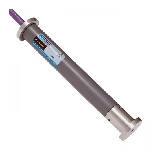
Embedment Strain Gauge
No part of this instruction manual may be reproduced, by any means, without the written consent of Geokon
®
.
The information contained herein is believed to be accurate and reliable. However, Geokon
®
assumes no responsibility for errors,
omissions or misinterpretation. The information herein is subject to change without notification.
Copyright © 2007-2019 by Geokon
®
(Doc REV E, 04/30/19)
Advertisement
Table of Contents

Summary of Contents for Geokon 3900
- Page 1 Instruction Manual Model 3900 Embedment Strain Gauge No part of this instruction manual may be reproduced, by any means, without the written consent of Geokon ® The information contained herein is believed to be accurate and reliable. However, Geokon ®...
- Page 3 Geokon or any breach of any warranty by Geokon shall not exceed the purchase price paid by the purchaser to Geokon for the unit or units, or equipment directly affected by such breach. Under no circumstances will Geokon reimburse the claimant for loss incurred in removing and/or reinstalling equipment.
-
Page 4: Table Of Contents
TABLE of CONTENTS 1. INTRODUCTION ..............................1 2. INSTALLATION ..............................1 3. TAKING READINGS ............................1 3.1 C .............................. 2 IRCUIT IAGRAM 3.2 U GK-502 R ..................... 2 SING THE EOKON EADOUT 4. DATA REDUCTION .............................. 3 4.1 D ........................... 3 ISPLACEMENT ALCULATION 4.2 S... -
Page 5: Introduction
The strain gauge can be read out by means of the Geokon Model 502 Readout Box or by a applying a 2 to 12 Volt excitation to the input leads and reading the corresponding millivolt output. -
Page 6: Circuit Diagram
3.1 Circuit Diagram Strain Gage Figure 1 - Circuit Diagram 3.2 Using the Geokon GK-502 Readout Box The user is referred to the GK-502 Instruction Manual for additional information on the following instructions: 1) Connect the embedment gauge to the readout box by means of the 10-pin input connector. -
Page 7: Data Reduction
4. DATA REDUCTION 4.1 Displacement Calculation The basic units utilized by Geokon for measurement and reduction of data from Model 3900 Embedment Strain Gauges are mV/V If a GK-502 readout box is in use mV/V can be displayed directly. The displacement D is given by the equation: D = ((R ) ×... -
Page 8: Temperature Correction Factor
4.3 Temperature Correction Factor Tests have shown that the temperature effect is such that the embedment gauge reading goes down (compression) as the temperature goes up and the required temperature correction factor is plus six microstrains per °C. So, for example, using the GK-502 (displaying mV/V) to take the readings, and a standard eight- inch-long gauge, where C is given in inches/mV/V, the calculation for strain S, corrected for temperature change (T ) measured in degrees Centigrade, is:... -
Page 9: Appendix A. Specifications
APPENDIX A. SPECIFICATIONS Standard Range¹: 5000 microstrain Accuracy: ± 0.1% FS Linearity: <0.5% FSR Resolution: ± 0.025% FSR Repeatability: 0.1% FSR Temperature Effect: 0.12% FSR/°C −20 to +80° C Temperature Range: 0 to 110° F Active Gauge Length 203 mm Input Resistance: 350Ω... -
Page 10: Appendix B. Thermistor Temperature Derivation
APPENDIX B. THERMISTOR TEMPERATURE DERIVATION Thermistor Type: YSI 44005, Dale #1C3001-B3, Alpha #13A3001-B3 Resistance to Temperature Equation: A+B ( LnR ) +C(LnR) -273.15 °C Equation 3 - Resistance to Temperature Where; T = Temperature in °C. LnR = Natural Log of Thermistor Resistance A = 1.4051 ×... -
Page 11: Appendix C. Typical Calibration Report
APPENDIX C. TYPICAL CALIBRATION REPORT Figure 2 - Typical Calibration Report...


Need help?
Do you have a question about the 3900 and is the answer not in the manual?
Questions and answers