Advertisement
Quick Links
DRW160444AB
Refrigeration Temperature Controller
TF3 SERIES
I N S T R U C T I O N M A U A L
Thank you for choosing our Autonics product.
Please read the following safety considerations before use.
Safety Considerations
※Please observe all safety considerations for safe and proper product operation to avoid hazards.
※Safety considerations are categorized as follows.
Warning Failure to follow these instructions may result in serious injury or death.
Caution Failure to follow these instructions may result in personal injury or product damage.
※The symbols used on the product and instruction manual represent the following
symbol represents caution due to special circumstances in which hazards may occur.
Warning
1. Fail-safe device must be installed when using the unit with machinery that may cause serious injury
or substantial economic loss. (e.g. nuclear power control, medical equipment, ships, vehicles,
railways, aircraft, combustion apparatus, safety equipment, crime/disaster prevention devices, etc.)
Failure to follow this instruction may result in personal injury, fire, or economic loss.
2. The unit must be installed on a device panel before use.
Failure to follow this instruction may result in electric shock.
3. Do not connect, repair, or inspect the unit while connected to a power source.
Failure to follow this instruction may result in electric shock.
4. Check the terminal numbers before connecting the power source.
Failure to follow this instruction may result in fire.
5. Do not disassemble or modify the unit. Please contact us if necessary.
Failure to follow this instruction may result in electric shock or fire.
Caution
1. Do not use the unit outdoors.
Failure to follow this instruction may result in shortening the life cycle of the unit, or electric shock.
2. When connecting the power input and relay output cables, use AWG 12 to 28 cables. (use the
appropriate wire by the rated output specification.) Make sure to tighten the relay output terminal
screw bolt 0.5N . m and the others communication and power terminal screw bolt 0.4N . m.
When connecting the sensor input cables, use AWG 14 to 30 cables and make sure to tighten the
terminal screw bolt 0.2N . m.
Failure to follow this instruction may result in fire due to contact failure.
3. Use the unit within the rated specifications.
Failure to follow this instruction may result in shortening the life cycle of the unit, or fire.
4. Do not use loads beyond the rated switching capacity of the relay contact.
Failure to follow this instruction may result in insulation failure, contact melt, contact failure, relay broken, or fire.
5. Do not use water or oil-based detergent when cleaning the unit. Use dry cloth to clean the unit.
Failure to follow this instruction may result in electric shock or fire.
6. Do not use the unit where flammable or explosive gas, humidity, direct sunlight, radiant heat,
vibration, or impact may be present.
Failure to follow this instruction may result in fire or explosion.
7. Keep dust and wire residue from flowing into the unit.
Failure to follow this instruction may result in fire or product damage.
Ordering Information
TF 3 3
3 4 H
T
No-mark No option
Option
S
Synchronize defrost
※2
function
T
RS485 communication
※3
R
RTC (real time clock)
※3
A
RS485 communication+RTC (real time clock)
Compressor
※1
load capacity
G
Compressor 20A 1a contact
A
Compressor 5A 1a contact
H
Compressor 16A 1c contact
Power supply
1
24VAC 50/60Hz, 12-24VDC
4
100-240VAC 50/60Hz
1CH 1
Compressor output
Compressor+Defrost or Auxiliary
Output
2
1CH,
(alarm/evaporator-fan) output
3CH
Compressor+Defrost+Auxiliary
3
(alarm/evaporator-fan) output
Number of input channels
1
1CH input (NTC or RTD) [temperature+digital input (DI)]
3CH input (NTC)
3
[inlet temperature+defrost temperature+
outlet temperature or digital input (DI)]
Digits
3
999 (3 digit)
Item
TF
Refrigeration Temperature Controller
※1: Only for 1CH input, compressor output model (TF31-1 G).
※2: Only for 3CH input model (TF33-
- ). Option function is varied by compressor load capacity and contact.
RS485
Option function
Synchronize
RS485
communi-
RTC function
Compressor
defrost function
communication
cation+RTC
load capacity & contact
function
Compressor 5A 1a
-
(TF33-
A-S)
(TF33-
A-T)
(TF33-3 A-A)
contact
Compressor 16A 1c
-
-
-
(TF33-3 H-R)
contact
※3: Except compressor+defrost or auxiliary (alarm/evaporator-fan) output model (TF33-2
※ Only for 3CH input, compressor+defrost+auxiliary (alarm/evaporator-fan) output model (TF33-3
supports buzzer.
※ The above specifications are subject to change and some models may be discontinued without notice.
Specifications
TF3 Series
Model
TF31-
Number of channels
1CH
Power
AC power
100-240VAC
50/60Hz
supply
AC/DC power 24VAC
50/60Hz, 12-24VDC
Allowable voltage range
90 to 110% of rated voltage
Power
AC power
Max. 8VA (100-240VAC
50/60Hz)
consumption
AC/DC power Max. 5VA (24VAC
50/60Hz), Max. 3W (12-24VDC )
Display method
7 Segment LED method (red)
Character size (W×H)
9.4×19.3mm
NTC
5kΩ/10kΩ
Input type
RTD
DPt100Ω
Sampling period
500ms
Display accuracy
At room temp. (23℃±5℃): ±1℃±1 digit
Compressor (COMP) 250VAC
5A 1a, 16A 1c, 20A 1a
Control
Defrost (DEF)
250VAC
10A 1a
output
Auxiliary (AUX)
250VAC
5A 1a
Communication output
-
Contact input: ON Max. 1㏀ , OFF Min. 100㏀
Digital input
No contact input: ON residual voltage: Max. 1V, OFF leakage current: Max. 1mA,
outflow current: 4㎂
Control method
ON/OFF control
Hysteresis
0.5 to 5.0℃, 2 to 10℉ variable
5A 1a
Mechanical: 5,000,000 operations, Electrical: 50,000 operations (250VAC 5A)
Compressor
16A 1c Mechanical: 20,000,000 operations, Electrical: 30,000 operations (250VAC 16A)
Relay
(COMP)
life
20A 1a Mechanical: 10,000,000 operations, Electrical: 100,000 operations (250VAC 20A)
cycle
Defrost (DEF)
Mechanical: 20,000,000 operations, Electrical: 100,000 operations (250VAC 10A)
Auxiliary (AUX)
Mechanical: 5,000,000 operations, Electrical: 50,000 operations (250VAC 5A)
Memory retention
Approx. 10 years (non-volatile memory method)
Insulation resistance
Min. 100MΩ (at 500VDC megger)
AC power
3000VAC 50/60Hz for 1 min (between all terminals and case, power and input circuit)
Dielectric
strength
AC/DC power 1000VAC 50/60Hz for 1 min (between all terminals and case, power and input circuit)
Noise resistance
Square-wave noise by the noise simulator (pulse width: 1㎲) ±2kV R-phase and S-phase
Vibration
1.5mm amplitude at frequency of 10 to 55Hz (for 1 min) in each X, Y, Z direction for 2 hours
Ambient temp. -10 to 50℃, storage: -20 to 60℃
Environment
Ambient humi. 35 to 85%RH, storage: 35 to 85%RH
Accessories
Bracket: 2, NTC sensor (5kΩ): 1
Protection structure
IP65 (front case)
Approval
※1
Weight
Approx. 207g (approx. 105g)
Remote display unit [TFD, sold separately]
Model
TFD-3
TFD-5
Vibration
Power supply
3.3VDC
Power consumption Max. 1W
Enviorn-
Ambient temp. -10 to 50℃, storage: -20 to 60℃
Display method 7 Segment LED method (red)
ment
Ambient humi. 35 to 85%RH, storage: 35 to 85%RH
Comm. method Serial (TTL Level), Half duplex Protection structure IP67
Comm. cycle
100ms
Approval
※1
Cable
Ø2.5mm, 3m
Ø2.5mm, 5m
Weight
※1. The weight includes packaging. The weight in parentheses is for unit only. The weight is varied by model option.
※Environment resistance is rated at no freezing or condensation.
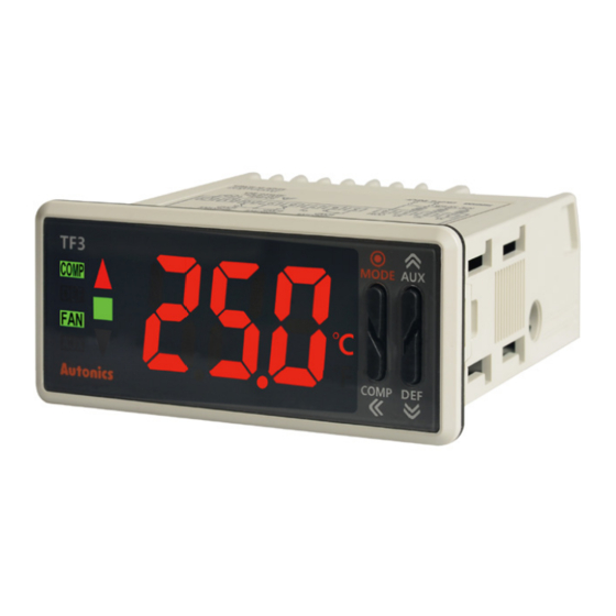
Part Description
1. Present value (PV) display component (red):
2
1
8 9
RUN mode: Displays present value (PV).
Setting mode: Displays parameter and setting value.
2. Deviation indicator (■: green, ▼/▲: red):
Displays deviation of present value (PV) based on
3
setting value (SV).
4
5
PV deviation
6
temperature
More than 1.8℃ ▲ indicator turns ON
Within ±1.8℃
7 11 10
Less than -1.8℃ ▼ indicator turns ON
3. Compressor (COMP) output indicator (green):
Turns ON for compressor output. In case of
compressor protection operation and output does not
turn ON, it flashes.
When operating compressor continuously, it turns ON
for 2 sec, and turns OFF for 1 sec.
12
4. Defrost (DEF) output indicator (green):
Turns ON for defrost output. Flashes for defrost delay operation.
Turns ON for 2 sec and OFF for 1 sec for manual defrost or Power ON defrost.
5. Evaporator-fan (FAN) output indicator (green):
Turns ON for evaporator-fan output. Flashes for delay operation of evaporator-fan output.
6. Auxiliary (AUX) output indicator (green):
Turns ON for alarm output. Flashes for delay operation of alarm output.
7. Unit indicator (red) : Displays temperature unit set at temperature unit [UNT] of parameter 1 group.
8.
(MODE) key: Used for entering parameter setting group, returning RUN mode, moving parameter or saving SV.
9.
(AUX) key : Used for entering SV setting group or changing setting value.
Hold the key over 3 sec to select active/inactive auxiliary output in RUN mode.
10.
(DEF) key: Used for entering SV setting group or changing setting value.
Hold the key over 3 sec to execute/stop manual defrost in RUN mode.
11.
(COMP) key :Used for entering SV setting group, changing setting value, moving digits.
Hold the key over 3 sec to active/inactive compressor output in RUN mode.
When buzzer alarm occurs, press the key once to stop the sound. (Only for 3CH input,
compressor+defrost+auxiliary (alarm/evaporator-fan) output model (TF33-3
Buzzer [BUZ] of parameter 1 group is set as [ON])
12. Data loader port:
It is for displaying TF3 data at remote display unit (TFD) by connecting phone-jack. In other case, for
connecting Autonics SCM-US (USB/Serial converter, sold separately), it is a PC loader port of serial
communication for parameter setting or monitoring by PC.
Input Type and Temperature Range
Input type
Decimal point Display method Temperature range (℃) Temperature range (℉)
1
N%H
-40 to 99
NTC 5kΩ
-40 to -20
0.1
N%L
-19.9 to 99.9
Thermistor
(NTC)
1
N!H
-40 to 99
No option
NTC 10kΩ
-40 to -20
0.1
N!L
-19.9 to 99.9
1
-99 to 99
DpH
-
※1
RTD
DPt 100Ω
-99 to -20
0.1
DpL
-19.9 to 99.9
(TF33-
H)
※ TF3 Series displays only 3 digits. If PV decimal number of shaded temperature range is out of 3 digit,
TF3 does not display the numbers below decimal point. You can check it at the comprehensive device
- )
- )
management program (DAQMaster) by communicating via PC.
※1: Only for 1CH input model (TF31-
).
※2: If PV with "-" sign is over 3 digits (e.g.: -99.9), the numbers below decimal point does not display. You can
check it at the comprehensive device management program (DAQMaster) by communicating via PC.
Connections
TF31-1 G
TF33-
-
COMP OUT
3CH
250VAC 20A
RESISTIVE LOAD
NTC 5K/10K
-
DPt100
Out of room temp. range: ±2℃±1 digit
SENSOR
DIGITAL INPUT
TF33-
A-
RS485 communication output
COMP OUT
DEF OUT
(Modbus RTU)
250VAC 5A
250VAC 10A
RESISTIVE
RESISTIVE
LOAD
LOAD
※1
S1 S2 S3 COM
A+
B-
NTC 5K/10K
SYNCHRONIZE
※3
/RS485
SENSOR
DIGITAL INPUT
※1: Only for compressor+defrost or auxiliary (alarm/evaporator-fan) output model (TF3 -2
※2: Only for compressor+defrost+auxiliary (alarm/evaporator-fan) output model (TF3 -3
※3: Only for synchronize defrost function model (TF33-
Dimensions
TF3 Series
77
1.5mm amplitude at frequency of 10 to 55Hz
(for 1 min) in each X, Y, Z direction for 2 hours
NTC sensor (5kΩ)
AWG22
TPE lead wire
Approx. 77g (approx. 48g)
Soldering
Max. 15
2000±50
TFD (sold separately)
Deviation display
3
12
52
indicator turns ON
Ø2.5,
3m or 5m
Remote Display Unit (TFD) [sold separately]
Remote display unit (TFD) displays current temperature or output status
of TF3 at remote place. TFD cable is TFD-3: 3m, TFD-5: 5m.
Connect the phone-jack of remote display unit (TFD) to the data loader
port of TF3. This unit is dedicated for TF3 Series and it does not directly
communicate with upper devices (PC, PLC, etc.)
If TFD communication with TF3 error occurs, TFD flashes display
component for 1 sec. Check the connection with TF3.
※ When connecting TFD to the data loader port of TF3, you cannot connect Autonics SCM-US (USB to Serial
converter, sold separately) for communication. Use SCM-US48I(USB to RS485 converter, sold separately),
SCM-38I(RS232C to RS485 converter, sold separately).
- ) supports buzzer.
SV Settings
You can set the temperature to control with
Set range is within SV low-limit value [LSV] to SV high-limit value [HSV].
E.g.) In case of changing SV from 19℃ to 10℃
①
-40 to 212
-40 to -20
-19.9 to 99.9
100 to 212
Press any key among
,
,
in RUN
-40 to 212
mode to enter into SV setting mode.
-40 to -20
Last digit (10
0
digit) on SV display part flashes.
-19.9 to 99.9
③
100 to 212
-148 to 212
-148 to 212
※2
Press
,
key to raise
or lower the set value. (9 → 0)
TF31-
A
COMP OUT
DEF OUT
AUX OUT
250VAC 5A
250VAC 10A
250VAC 5A
RESISTIVE
RESISTIVE
RESISTIVE
※1
※2
LOAD
LOAD
LOAD
NTC 5K/10K
SOURCE
SOURCE
100-240VAC 50/60Hz,
100-240VAC 50/60Hz,
24VAC 50/60Hz,
DPt100
24VAC 50/60Hz,
12-24VDC
SENSOR
12-24VDC
DIGITAL INPUT
TF33-
H-
AUX OUT
COMP OUT
DEF OUT
AUX OUT
250VAC 5A
250VAC 16A
250VAC 10A
250VAC 5A
RESISTIVE
RESISTIVE
RESISTIVE
RESISTIVE
LOAD
※2
※1
※2
LOAD
LOAD
LOAD
S1 S2 S3 COM
SOURCE
NTC 5K/10K
SOURCE
100-240VAC 50/60Hz,
100-240VAC 50/60Hz,
SENSOR
24VAC 50/60Hz,
DIGITAL INPUT
24VAC 50/60Hz,
12-24VDC
12-24VDC
- ), compressor+defrost+auxiliary (alarm/evaporator-fan) output model(TF3 -3
- ).
A-S), or RS485 communication model (TF33-
A-T/A).
Comprehensive Device Management Program
(unit: mm)
[DAQMaster]
5.5
74.3
DAQMaster is comprehensive device management program. It is available for parameter setting, monitoring ,
and user parameter group setting, parameter mask setting for only TF3 Series. DAQMaster can be downloaded
from our web site at www.autonics.com.
Item
Minimum specifications
System
IBM PC compatible computer with Pentium Ⅲ or above
Operations
Windows 98/NT/XP/Vista/7/8/10
Memory
256MB+
Bracket
Hard disk
1GB+ of available hard disk space
VGA
Resolution: 1024×768 or higher
Others
RS232C serial port (9-pin), USB port
46
Parameter Mask
This function is able to hide unnecessary parameters to user environment or less frequently used parameters in
parameter group. You can set this in the comprehensive device management program (DAQmaster).
Masked parameters are only not displayed. The setting value of masked parameters are applied.
5±1
12
For more information, refer to DAQMaster user manual.
23.9
Visit our web site (www.autonics.com) to download DAQmaster program and the user manual.
Before applying mask
Panel cut-out
After applying mask
A
The above is masking input sensor 3 selection [S3], temperature unit [UNT] of parameter 1 group for 3CH input
model (TF33-
- ).
D
B
Parameter User Group [PAU]
C
(unit: mm)
This function is able to set the frequently used parameters to the user parameter group. You can quickly and
easily set parameter settings. User parameter group can have up to 30 parameters in the comprehensive device
Size
A
B
C
D
Series
management program (DAQMaster).
※1
For more information, refer to the DAQMaster user manual.
TF3
Min. 100
Min. 55 70.3
+ 0.7
28.2
+ 0.5
0
0
Visit our web site (www.autonics.com) to download the DAQMaster program and the user manual.
TFD
Min. 65
Min. 40 45.7
+ 0.6
25.4
+ 0.3
0
0
※1. When connecting remote display unit (TFD),
RUN mode
or SCM-US, Min. 120
PAU
PA1
DsT
HYS
The above is setting user parameter group in the DAQMaster with delay display period [DsT] of parameter 1
group, hysteresis [HYS], night mode hysteresis [nHY] of parameter 2 group, defrost method [DEF], defrost time
[DET] of parameter 3 group, alarm output hysteresis [aHY] of parameter 4 group.
Virtual Temperature Rate [VtR]
(only for 3CH input model: TF33-
In case of 3CH input model (TF33-
temperature [TS]. You can set virtual temperature rate.
If the temperature of inlet and outlet is significantly different at freezer, virtual temperature helps to control
temperature efficiently.
Virtual temperature is designated by the rate of input sensor 1 (inlet temperature) and input sensor 3 (outlet
,
,
keys.
temperature). There is virtual temperature calculation formula.
Virtual temperature (PV)=
②
If virtual temperature rate [VtR] is set as [0], virtual temperature (PV)= input sensor 1.
If virtual temperature rate [VtR] is set as [100], virtual temperature (PV)= input sensor 3
E.g.) If inlet temperature of input sensor 1 is 0℃, and outlet temperature of input sensor 3 is 10℃,
set virtual temperature rate [VtR] as [50] and virtual temperature is 5℃ to control temperature.
[{100-50}×0]+ [50×10]
Press
key to move digit.
5=
(10
0
→ 10¹→ 10²→10³→ 10
0
)
Setting range of virtual temperature rate: 0 to 100 (%)
Display Selection [DpT]
④
(only for 3CH input model: TF33-
You can select input sensor to display at present value (PV) display component in RUN mode.
Parameter Description
S1
Displays PV of input sensor 1 (inlet temperature).
Press
(MODE) key to save the set value.
Displays PV of input sensor 2 (defrost temperature).
S2
If there is no additional key operations in 3 sec,
Displays PV of input sensor 3 (outlet temperature).
S3
the changed SV is automatically saved.
VS
Displays virtual temperature.
TF31-
H
COMP OUT
DEF OUT
AUX OUT
250VAC 16A
250VAC 10A
250VAC 5A
RESISTIVE
RESISTIVE
RESISTIVE
※1
※2
LOAD
LOAD
LOAD
NTC 5K/10K
SOURCE
100-240VAC 50/60Hz,
DPt100
24VAC 50/60Hz,
SENSOR
DIGITAL INPUT
12-24VDC
- ).
PA1
INT
S2
S3
VtR
UNT
PA1
INT
S2
VtR
PA5
nHY
DEF
DET
aHY
- )
- ), input sensor 3 selection [S3] of parameter 1 group is set as outlet
[{100-virtual temperature rate} × input sensor 1 temperature]
+ [virtual temperature rate × input sensor 2 temperature]
100
100
- )
Advertisement

Subscribe to Our Youtube Channel
Related Manuals for Autonics TF3 Series


Summary of Contents for Autonics TF3 Series
- Page 1 Parameter Description (TF33-3 H-R) (TF33- ※ TF3 Series displays only 3 digits. If PV decimal number of shaded temperature range is out of 3 digit, contact ※3: Except compressor+defrost or auxiliary (alarm/evaporator-fan) output model (TF33-2 TF3 does not display the numbers below decimal point. You can check it at the comprehensive device Displays PV of input sensor 1 (inlet temperature).
- Page 2 RUN mode. Comp. min. operation cycle [CYC] Defrost when power ON [pDE] OFF No digital input If you forget password, contact Autonics after checking PA 1 group lock [lP1] Parameter Factory default Parameter Factory default Parameter...
Need help?
Do you have a question about the TF3 Series and is the answer not in the manual?
Questions and answers