Advertisement
TCD210237AB_MODI
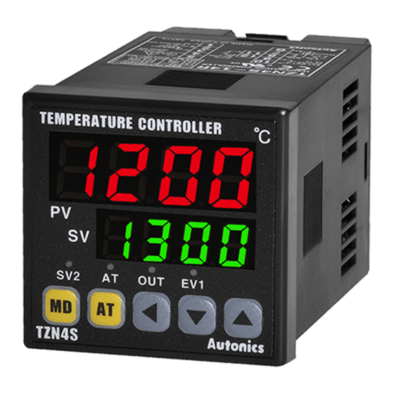
Dual-Speed PID Temperature
Controllers
TZ / TZN Series
PRODUCT MANUAL
For your safety, read and follow the considerations written in the instruction
manual, other manuals and Autonics website.
The specifications, dimensions, etc are subject to change without notice for product
improvement Some models may be discontinued without notice.
Features
• Dual-speed PID control
- High-speed response : minimizes time required to reach SV
- Low-speed response : minimizes overshoot for sensitive temperature control
• High display accuracy : ±0.3% of full-scale value
• 2-step auto tuning function
• Various input types (13 total) : includes temperature sensor and analog inputs
• Various sub-output options
- Various alarm outputs including loop break alarm and sensor break alarm
- PV transmission output (DC 4-20mA)
- RS485 Communication output
• Decimal point display function for analog inputs
ᜢ ᜧ ᜫ
Safety Considerations
• Observe all 'Safety Considerations' for safe and proper operation to avoid hazards.
• symbol indicates caution due to special circumstances in which hazards may occur.
Warning
Failure to follow instructions may result in serious injury or death
01. Fail-safe device must be installed when using the unit with machinery that
may cause serious injury or substantial economic loss.(e.g. nuclear power
control, medical equipment, ships, vehicles, railways, aircraft, combustion
apparatus, safety equipment, crime/disaster prevention devices, etc.)
Failure to follow this instruction may result in personal injury, economic loss or fire.
02. Do not use the unit in the place where flammable/explosive/corrosive gas,
high humidity, direct sunlight, radiant heat, vibration, impact or salinity
may be present.
Failure to follow this instruction may result in explosion or fire.
03. Install on a device panel to use.
Failure to follow this instruction may result in electric shock.
04. Do not connect, repair, or inspect the unit while connected to a power
source.
Failure to follow this instruction may result in fire or electric shock.
05. Check 'Connections' before wiring.
Failure to follow this instruction may result in fire.
06. Do not disassemble or modify the unit.
Failure to follow this instruction may result in fire or electric shock.
Caution
Failure to follow instructions may result in injury or product damage
01. When connecting the power input and relay output, use AWG 20 (0.50 mm
cable or over, and tighten the terminal screw with a tightening torque of 0.74
to 0.90 N m.
When connecting the sensor input and communication cable without
dedicated cable, use AWG 28 to 16 cable and tighten the terminal screw with
a tightening torque of 0.74 to 0.90 N m..
Failure to follow this instruction may result in fire or malfunction due to contact
failure.
02. Use the unit within the rated specifications.
Failure to follow this instruction may result in fire or product damage
03. Use a dry cloth to clean the unit, and do not use water or organic solvent.
Failure to follow this instruction may result in fire or electric shock.
04. Keep the product away from metal chip, dust, and wire residue which flow
into the unit.
Failure to follow this instruction may result in fire or product damage.
Cautions during Use
• Follow instructions in 'Cautions during Use' . Otherwise, it may cause unexpected
accidents.
• Check the polarity of the terminals before wiring the temperature sensor. For RTD
temperature sensor, wire it as 3-wire type, using cables in same thickness and length.
For thermocouple (TC) temperature sensor, use the designated compensation wire for
extending wire.
• Keep away from high voltage lines or power lines to prevent inductive noise. In case
installing power line and input signal line closely, use line filter or varistor at power line
and shielded wire at input signal line. Do not use near the equipment which generates
strong magnetic force or high frequency noise.
• Install a power switch or circuit breaker in the easily accessible place for supplying or
disconnecting the power.
)
2
Advertisement
Table of Contents

Related Manuals for Autonics TZ Series


Summary of Contents for Autonics TZ Series
- Page 1 For your safety, read and follow the considerations written in the instruction • Follow instructions in ‘Cautions during Use’ . Otherwise, it may cause unexpected manual, other manuals and Autonics website. accidents. The specifications, dimensions, etc are subject to change without notice for product •...
-
Page 2: Ordering Information
S: DIN W 48 × H 48 mm (TZN Series) R: Relay output • Control output: ≥ 10,000,000 operations SP: DIN W 48 × H 48 mm (11 pin type, TZ Series) S: SSR drive output Mechanical • Option output: ≥ 20,000,000 operations ST: DIN W 48 ×... -
Page 3: Input Type Setting
32 to 932 DPtH DPt100Ω 0.1 -199.9 to 199.9 -199.9 to 391.8 • Unit: mm, For the detailed drawings, follow the Autonics website. DPtL 0 - 10 VDCᜡ A--1 -1999 to 9999 Voltage • Below is based on TZ4ST Series. -
Page 4: Crimp Terminal Specifications
-|Transparent Guide|- Connections ■ TZ4W/TZN4W PV OUT DC4-20mA MAIN OUT ■ TZ4SP SOURCE 250 VACᜠ 3A 1c 100-240 VACᜠ SV2 IN 30 VDCᜡ 3A 1c RS485 RS485 50/60 Hz 6VA Max. 5 VDCᜡ 250 ㎂ Resistive load (A+) (B-) 17 16 15 14 13 12 11 10 9 SOURCE 100-240 VACᜠ... -
Page 5: Parameter Setting
-|Transparent Guide|- SV2 Setting Parameter Setting It is possible to control an additional temperature value at a desired range by using SV2. • Some parameters are activated/deactivated depending on the model or setting of other parameters. Refer to the descriptions of each item. Connect a contact signal (under 5 VDC , 250 ㎂) at the external terminal, to operate in ᜡ... - Page 6 When power is supplied and it is an alarm standby condition, this first alarm condition is ignored and from the sequence second 1alarm condition, alarm latch operates. Segment Table The segments displayed on the product indicate the following meanings. It may differ depending on the product. 7 Segment 11 Segment 12 Segment 16 Segment 18, Bansong-ro 513Beon-gil, Haeundae-gu, Busan, Republic of Korea, 48002 www.autonics.com | +82-2-2048-1577 | sales@autonics.com...
Need help?
Do you have a question about the TZ Series and is the answer not in the manual?
Questions and answers