Autonics TM Series User Manual
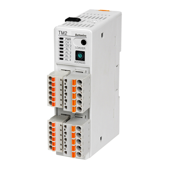
Multi-ch modular type temperature controller
Hide thumbs
Also See for TM Series:
- User manual (98 pages) ,
- User manual for communication (36 pages) ,
- Manual (9 pages)
Table of Contents
Advertisement
Advertisement
Table of Contents

Related Manuals for Autonics TM Series


Summary of Contents for Autonics TM Series
- Page 1 Preface USER MANUAL © Copyright Reserved Autonics Co., Ltd.
- Page 2 Preface © Copyright Reserved Autonics Co., Ltd.
-
Page 3: Preface
Preface Preface Thank you for purchasing an Autonics product. Please familiarize yourself with the information contained in the Safety Precautions section before using this product. This user manual contains information about the product and its proper use, and should be kept in a place where it will be easy to access. -
Page 4: User Manual Guide
The manual's content may vary depending on changes to the product's software and other unforeseen developments within Autonics, and is subject to change without prior notice. Upgrade notice is provided through out homepage. We contrived to describe this manual more easily and correctly. However, if there are any ... -
Page 5: User Manual Symbols
Failure to follow instructions can result in serious injury or death. Failure to follow instructions can lead to a minor injury or product damage. An example of the concerned feature's use. Annotation mark. ※1 © Copyright Reserved Autonics Co., Ltd. -
Page 6: Safety Considerations
Failure to follow this instruction may result in fire or explosion. Keep metal chip, dust, and wire residue from flowing into the unit. Failure to follow this instruction may result in fire or product damage. © Copyright Reserved Autonics Co., Ltd. -
Page 7: Caution During Use
④Installation category II The above specifications are subject to change and some models may be discontinued without notice. Be sure to follow cautions written in the instruction manual, user manual and the technical descriptions (catalog, homepage). © Copyright Reserved Autonics Co., Ltd. - Page 8 Caution during Use VIII © Copyright Reserved Autonics Co., Ltd.
-
Page 9: Table Of Contents
Temperature control examples ................38 5.3.1 Single module .................... 38 5.3.2 Multiple modules ..................40 Parameter Settings and Functions ............41 Input ........................41 6.1.1 Input type and temperature range .............. 41 6.1.2 Input type ....................42 © Copyright Reserved Autonics Co., Ltd. - Page 10 6.6.3 Cooling MV monitoring ................81 6.6.4 Heater current monitoring ................81 Run/Stop function ....................82 6.7.1 Control output for STOP ................82 6.7.2 Alarm output for STOP ................82 Multi SV ........................83 © Copyright Reserved Autonics Co., Ltd.
- Page 11 Error ........................85 6.10.1 Sensor error, MV setting ................85 6.11 Parameter initialization .................... 86 Simple Error Diagnosis ................87 Error display ......................87 Trobleshootings ....................... 87 DAQMaster ....................89 Overview ......................... 89 Features ........................90 © Copyright Reserved Autonics Co., Ltd.
- Page 12 Table of Contents © Copyright Reserved Autonics Co., Ltd.
-
Page 13: Product Introduction
Product Introduction Features TM Series module type temperature controller realizes high-speed controlling with superior sampling cycle (TM4 – 100 ms, TM2 – 50 ms). Side connector connection makes less wiring work and close mounting possible for up to 31 units without additional power and communication wires for expansion modules. -
Page 14: Components And Accessories
Note that power supply/communications connectors are provided with basic modules only. (2) Accessories (sold separately) Communication converter SCM-WF48 (Wi-Fi to RS485·USB SCM-US48I wireless communication converter) (USB to RS485 converter) SCM-38I SCM-US (USB to Serial converter) (RS232C to RS485 converter) © Copyright Reserved Autonics Co., Ltd. - Page 15 1 Product Introduction Current transformer(CT) CSTC-E80LN • Max. load current: 80A(50/60Hz) ※Max. load current for TM Series is 50A. • Current ratio: 1/1000 • Wire wounded resistance: 31Ω±10% (unit: mm) © Copyright Reserved Autonics Co., Ltd.
- Page 16 1 Product Introduction CSTC-E200LN • Max. load current: 200A(50/60Hz) ※Max. load current for TM Series is 50A. • Current ratio: 1/1000 • Wire wounded resistance: 20Ω±10% (unit: mm) © Copyright Reserved Autonics Co., Ltd.
- Page 17 1 Product Introduction CSTS-E80PP Max. load current: 80A (50/60Hz) ※Max. load current for TM Series is 50A. Current ratio: 1/1000 Wire wounded resistance: 31Ω ±10% (unit: mm) For using CT, do not supply first part current when opening CT output.
- Page 18 DS/DA-T Series (RS485 communication input type display unit) Connect RS485 communication input type display unit (DS/DA-T Series) and TM Series, the display unit displays present value of the device without PC/PLC. Images of components and accessories may differ from actual products.
-
Page 19: Models
Selectable current or SSR drive output ⑤ Control output Relay output 4-channel SSR drive output Basic module ⑥ Module type ※ 1 Expansion module ※1. The expansion module does not supply power/comm. terminal. Order it with the basic module. © Copyright Reserved Autonics Co., Ltd. -
Page 20: Model List And Descriptions
RS485 comm. output Current or Alarm 1/2/3/4, TM2-42CE SSR drive RS485 comm. output output TM4-N2RB Relay output Basic SSR drive module TM4-N2SB output RS485 comm. output Series TM4-N2RE Relay output Expansion SSR drive module TM4-N2SE output © Copyright Reserved Autonics Co., Ltd. -
Page 21: Parts And Features
Control output Initial power ON Auto-tuning ※2 Indicator ※ 3 PWR (green) CH1 (red) Flashes (2,400bps) Flash CH2 (red) Flashes (4,800bps) Flash CH3 (red) Flashes (9,600bps) Flash CH4 (red) Flashes (19,200bps) Flash Flashes (38,400bps) © Copyright Reserved Autonics Co., Ltd. - Page 22 Lock switch: Used for fixing modules at top and bottom. ⑨ Rail Lock: Used for installing at DIN rail or using bolts. ⑩ END cover: Remove it when connecting each module to connect an expansion connector. ⑪ © Copyright Reserved Autonics Co., Ltd.
-
Page 23: Other Parts
1 Product Introduction 1.4.2 Other parts © Copyright Reserved Autonics Co., Ltd. - Page 24 1 Product Introduction © Copyright Reserved Autonics Co., Ltd.
-
Page 25: Specifications
Solid-state input: ON residual ● Digital input voltage max. 1.5VDCᜡ, OFF leakage current max. 0.1mA Outflow current: ● Approx. 0.5mA per input Hysteresis 1 to 100℃/℉ (0.1 to 100.0℃/℉) variable Proportional band (P) 0.1 to 999.9℃/℉ © Copyright Reserved Autonics Co., Ltd. - Page 26 ※2. Applied when it is for out of room temperature (23±5℃) range. ※3. The weight includes packaging. The weight in parenthesis is for unit only. ※Environment resistance is rated at no freezing or condensation. © Copyright Reserved Autonics Co., Ltd.
-
Page 27: Dimensions
3 Dimensions Dimensions (unit: mm) Expansion modules do not have a power supply/communications connection terminal at the bottom. Installation 3.1.1 Connector connection Expansion modules do not have a power supply/communications connection terminal. © Copyright Reserved Autonics Co., Ltd. -
Page 28: Module Connection
3.1.2 Module connection TM Series allows simulataneous monitoring for multi channel I/O with connecting Multiple modules using module expansion connectors. Connect expansion modules to a basic module. Basic module can be placed in any position among multiple module sets. Remove the cover. -
Page 29: Mounting With Bolts
2nd Insert bolts to fix it on rail lock. (fixing torque is 0.5 to 0.9 N•m). 3.1.4 Mounting on DIN rail (1) Installation/Removal method of a single module Installing 1st Hang the top rail lock to DIN rail. 2nd Push and press the module to down direction. © Copyright Reserved Autonics Co., Ltd. - Page 30 2nd Mount the module body to the DIN rail and then push the rail lock in. Removing 1st Pull each rail lock switch up and down. 2nd Remove the body from the DIN rail. © Copyright Reserved Autonics Co., Ltd.
-
Page 31: Connections And Insulation Block Diagram
4 Connections and Insulation Block Diagram Connections and Insulation Block Diagram TM2 Series ※ Relay AL3/AL4 OUT are available only for TM2-42□□ models. Power/Comm. connection terminal [Only for basic module: TM□-□□□B] © Copyright Reserved Autonics Co., Ltd. -
Page 32: Tm4 Series
It is recommended to use lines with AWG28 to 14 when connecting the sensor or compensation wire. It is recommended to use lines thicker than AWG24 for SSR drive output. It is recommended to use lines with AWG26 to 12 for relay output. © Copyright Reserved Autonics Co., Ltd. -
Page 33: Wiring Precautions
Do not put the sensor lines in close proximity of the AC power lines. Make sure the sensor is completely inserted in the connector using a crimped terminal. Fix the sensor to the connecter properly for accurate measurement. © Copyright Reserved Autonics Co., Ltd. -
Page 34: Power Supply Connection
Do not tie the communications line together with the AC power line. Use twisted pair cables for the communications line only. Do not allow the communication line to exceed 800m in length. For further details, please refer to ‘6.5 Communications’. © Copyright Reserved Autonics Co., Ltd. -
Page 35: Module Connection
4 Connections and Insulation Block Diagram 4.3.4 Module connection (1) Basic module positioning The basic module can be mounted anywhere in the connected group. It works regardless of communication address. © Copyright Reserved Autonics Co., Ltd. - Page 36 31 modules can be connected at the same time. Maximum required power = 31 X 5 W = 155 W When connecting several module sets (31 modules or less), each module set requires separate power supply. © Copyright Reserved Autonics Co., Ltd.
-
Page 37: Preparation And Startup
General process Before operating TM Series for the first time, do the following: 1st Connect all external devices, sensor and load to the TM Series. 2nd Set parameter values through external connecting devices (PC loader program, GP etc.). 3rd Download the parameters to TM Series. -
Page 38: Temperature Control Examples
(1) TM4-N2RB model (relay output) ※1. Using SCM-US enables only setting parameter. To monitor and control temperature requires the additional 24VDC power supply. Do not connect SCM-US and RS485 communications cables at the bottom at the same time. © Copyright Reserved Autonics Co., Ltd. - Page 39 ※1. Using SCM-US enables only setting parameter. To monitor and control temperature requires the additional 24VDC power supply. Do not connect SCM-US and RS485 communications cables at the bottom at the same time. Use an isolated type SSR. © Copyright Reserved Autonics Co., Ltd.
-
Page 40: Multiple Modules
5 Preparation and Startup 5.3.2 Multiple modules © Copyright Reserved Autonics Co., Ltd. -
Page 41: Parameter Settings And Functions
※2. G(TT) : Same as existing W(TT) type temperature sensor. Temperature sensors convert subject temperature to electrical signals for the temperature controller, allowing it to control output. SV (setting value) can only be set within the input range. © Copyright Reserved Autonics Co., Ltd. -
Page 42: Input Type
When modifying the temperature units, setting values of the related parameters remain the same as the existing values, and SV, Multi SV No., SV-0 to SV-3, SV high-limit/low-limit, and input correction will be initialized. © Copyright Reserved Autonics Co., Ltd. -
Page 43: Input Correction
When the Input Digital Filter is set to 0.4 seconds, the digital filter is applied according to a sampling value collected over 0.4 seconds (400ms). When the Input Digital Filter is used, PV (present value) can vary from the actual input value. © Copyright Reserved Autonics Co., Ltd. -
Page 44: High/Low-Limit Value
SV low-limit cannot exceed SV high-limit. Changing the input sensors automatically changes the SV high/low-limit settings to max/min values of the changed input sensor input. The user is required to reset related settings. © Copyright Reserved Autonics Co., Ltd. -
Page 45: Control Output
(heater) if PV (present value) falls below SV (setting value). (2) Cooling control Cooling control mode: the output will be provided in order to supply power to the load (cooler) if PV (present value) rises above SV (setting value). © Copyright Reserved Autonics Co., Ltd. - Page 46 Cooling output: Relay output fixed CH2 OUT AL2 OUT For TM2 Series, heating output can be selected by models from relay output, SSR drive output and current output. Cooling output is fixed to relay output. © Copyright Reserved Autonics Co., Ltd.
-
Page 47: Deadband/Overlap Band
Set deadband to 0 when a deadband or an overlap band is not used. When proportional bands are different, the smaller one takes precedence. Input sensor (H, L) setting determines the use of a decimal point. © Copyright Reserved Autonics Co., Ltd. - Page 48 6 Parameter Settings and Functions (1) Using Deadband © Copyright Reserved Autonics Co., Ltd.
- Page 49 6 Parameter Settings and Functions (2) Using Overlap band © Copyright Reserved Autonics Co., Ltd.
- Page 50 6 Parameter Settings and Functions (3) Using neither Deadband nor Overlap Band © Copyright Reserved Autonics Co., Ltd.
-
Page 51: Mv High/Low-Limit Value
MV high/low-limit values are not applied to manual control, MV upon control stop, MV upon a sensor error, and initial manual control MV. MV high/low-limit value configuration is not available for ON/OFF control in standard control mode (heating or cooling control). © Copyright Reserved Autonics Co., Ltd. -
Page 52: Ramp Function
OPEN, HHHH, LLLL, after Auto-tuning, PV = SV Inactive conditions. Power On, SV change, switch from STOP to RUN, switch from Manual to Auto, Ramp Rate or Ramp time unit When not 0 Active change © Copyright Reserved Autonics Co., Ltd. - Page 53 6 Parameter Settings and Functions Example Ramp graph © Copyright Reserved Autonics Co., Ltd.
-
Page 54: Auto/Manual Control
PRESET-MV: Apply preset MV as the initial MV. Preceding Setting Factory Setting group Parameter Unit condition range default AUTO-MV: Control Setting Initial Manual MV AUTO-MV: PRESET-MV: Reverting to power, the control starts with the MV of the power off. © Copyright Reserved Autonics Co., Ltd. -
Page 55: Manual Control Initial Mv
Initial Setting Current Output Range 0-20, 4-20 4-20 If the model is TM2-□□C□ (current or SSR drive output type), the relevant parameter will be activated only if the control output is set to current. © Copyright Reserved Autonics Co., Ltd. -
Page 56: Temperature Control
0.1 to 100.0(L) Heating 0 to 100(H) Heating_OFF Heating Offset 0.0 to 100.0(L) Control & Digit Operation 1 to 100(H) Cooling_ON Cooling Hysteresis 0.1 to 100.0(L) Cooling 0 to 100(H) Cooling_OFF Offset 0.0 to 100.0(L) © Copyright Reserved Autonics Co., Ltd. -
Page 57: Pid Control
Sec. Operation Cooling, PID Cooling_Integral Time Integral control is not conducted if the integral time is set to 0. Setting the integral time too short can intensify Correction Movements and cause hunting. © Copyright Reserved Autonics Co., Ltd. - Page 58 Heating, PID Heating_ Control Time 20.0 (RY) 0.1 to Initial Setting Sec. 120.0 2.0 (SSR) Cooling, PID Cooling_ Control Time If using heating and cooling control, configure each control period separately for heating and cooling. © Copyright Reserved Autonics Co., Ltd.
- Page 59 Applicable only when integral time is set to 0 (under P control or PD control only). Switching from heating and cooling control to standard control (P, PD control) automatically configures the reset setting to 50%. © Copyright Reserved Autonics Co., Ltd.
-
Page 60: Auto-Tuning
When auto-tuning is in progress and digital input(DI-1,DI-2) feature is run/stop or auto/manual, auto-tuning will be automatically ended, if concerned DI is inputted or sensor break error occurs. Auto-tuning is not available in manual control. © Copyright Reserved Autonics Co., Ltd. - Page 61 Unit group condition range default TUN1 Auto-Tuning Initial Setting TUN 1 Mode TUN 2 In cooling control mode, TUN2 Mode calculates 70% based at 0°. E.g.) If SV is -100, executes TUN2 at -70. © Copyright Reserved Autonics Co., Ltd.
-
Page 62: Alarm Output
CH1 and CH2, Alarm 2, 4: CH2 CH1 or CH2 In case of heating/cooling control, Alarm 1 and Alarm 2 are used as a cooling control output; therefore, they cannot be used as an alarm output. © Copyright Reserved Autonics Co., Ltd. -
Page 63: Alarm Output Operating Mode
On if current transformer (CT) detects Heater burnout alarm heater break. Setting group Parameter Setting range Factory default Unit Alarm 1, 3: AL-1 Refer to the Alarm Setting Alarm Mode above table. Alarm 2, 4: AL-2 © Copyright Reserved Autonics Co., Ltd. -
Page 64: Alarm Output Option
You can set alarm output (Alarm 1 Type to Alarm 4 Type) individually. If alarm output mode has been selected as LBA, SBA or HBA, AL-C, AL-D modes are not available. © Copyright Reserved Autonics Co., Ltd. -
Page 65: Alarm Sv
Alarm Low_Ch Within the temperature range of input type Changing the alarm output mode or options resets the settings to the highest or lowest values that will not trigger output in the new mode. © Copyright Reserved Autonics Co., Ltd. -
Page 66: Alarm Output Hysteresis
Setting group Parameter Setting range Unit default Alarm Setting Alarm NO/NC NO, NC Front indicators Change Alarm occurs Alarm output Indicator Open □ OFF N.O. Close ■ ON Close □ OFF N.C. Open ■ ON © Copyright Reserved Autonics Co., Ltd. -
Page 67: Alarm Output Delay
Setting Setting Parameter Factory default Unit group range Alarm ON Delay Time 0 to 3600 Sec. Alarm Setting Alarm OFF Delay 0 to 3600 Sec. © Copyright Reserved Autonics Co., Ltd. -
Page 68: Loop Break Alarm(Lba)
When executing auto-tuning, LBA detection band (LBA Band) and LBA monitoring time(LBA Time) is automatically set based on auto-tuning value. In case of AT (auto-tuning)/manual control/stop control, loop break alarm (LBA) does not operates. When alarm reset is input, it initializes LBA monitoring start time. © Copyright Reserved Autonics Co., Ltd. - Page 69 Temperature L: 002.0 to 100.0 (℃/℉) Temperature H: 0002 to 010.0 (℃/℉) Factory Setting group Parameter Setting range Unit default LBA Band Ch1, 0 to 999 (H) Alarm Setting ℃/℉ LBA Band Ch2 0.0 to 999.9 (L) © Copyright Reserved Autonics Co., Ltd.
- Page 70 (LBA Band) during LBA monitoring time (LBA Time), loop break alarm (LBA) turns OFF after LBA monitoring time (LBA Time). ⑧ to ⑨ The status of changing control output MV (LBA monitoring time is reset.) © Copyright Reserved Autonics Co., Ltd.
-
Page 71: Sensor Break Alarm
Current detection is not performed if OUT control output time is less than 250 ms. It is recommended to use Autonics designated current transformer (for 50 A). Alarm output option can be set to standard alarm (AL-A) or alarm latch (AL-B). - Page 72 10 A (5 A×2). If a single heater burns out, the heater current becomes 5A. The setting value is calculated as (10 A + 5 A)/2 = 7.5 A). Heater current values of less than 7.5 A (heater burnout setting value) are deemed heater burnout and the alarm activates. © Copyright Reserved Autonics Co., Ltd.
-
Page 73: Alarm Output Off
You can assign the digital input terminals (DI-1, DI-2) for the alarm output off feature. For more information about digital terminal (DI) setting, please refer to '6.9.1 Digital input terminal ’. After deactivating the alarm output, it will function normally for the next alarm output occurrence. © Copyright Reserved Autonics Co., Ltd. -
Page 74: Alarm Output Examples
6 Parameter Settings and Functions 6.4.12 Alarm output examples (1) Absolute value high-limit alarm and deviation high-limit alarm ※HYS: Hysteresis (2) Absolute value low-limit alarm and deviation low-limit alarm ※HYS: Hysteresis © Copyright Reserved Autonics Co., Ltd. - Page 75 6 Parameter Settings and Functions (3) Deviation high/low-limit alarm ※HYS: Hysteresis (4) Deviation high/low-limit reverse alarm ※HYS: Hysteresis © Copyright Reserved Autonics Co., Ltd.
- Page 76 6 Parameter Settings and Functions (5) Deviation high/low-limit alarm (hysteresis overlap) ※HYS: Hysteresis © Copyright Reserved Autonics Co., Ltd.
-
Page 77: Communications
Users can set communication address using both SW1 (communication address setting switch) and SW2 (communication group change switch). Setting range: 01 to 31 Factory default: [SW1] 1, [SW2] +0 If 00 is designated, communications are not performed. © Copyright Reserved Autonics Co., Ltd. -
Page 78: Communications Speed Settings
Sets the total bits with signal value of 1 as even numbers. Sets the total bits with signal value of 1 as odd numbers. Factory Setting group Parameter Setting range Unit default Communication Setting Parity Bit NONE, EVEN, ODD NONE © Copyright Reserved Autonics Co., Ltd. -
Page 79: Communication Stop Bit
Parameter set/change enable via communication. DISABLE Prohibit parameter setting or modification via communication. Factory Setting group Parameter Setting range Unit default Communication Communication Setting ENABLE, DISABLE ENABLE Write Reading parameter settings is always permitted. © Copyright Reserved Autonics Co., Ltd. -
Page 80: Usb-To-Serial Connection
6 Parameter Settings and Functions 6.5.7 USB-to-Serial connection Data can be transmitted via a USB-to-serial connection. However, RS485 communication through a USB-to-serial connection is blocked by hardware. © Copyright Reserved Autonics Co., Ltd. -
Page 81: Monitoring Function
Control output type Heater current monitoring TM□-□□R□ (Relay output) Relay output ○ TM4□-□□S□ ON/OFF control ○ (SSR drive output) Cycle control Phase control TM2□-□□C□ Current output (Current or SSR drive output) SSR drive output ○ © Copyright Reserved Autonics Co., Ltd. -
Page 82: Run/Stop Function
Factory Setting group Parameter Setting range Unit default Control Setting Stop Alarm Out CONTINUE, OFF CONTINUE © Copyright Reserved Autonics Co., Ltd. -
Page 83: Multi Sv
Control Setting Multi SV 1EA, 2EA, 4EA Numbers Control Operation Multi SV Multi SV No. SV-0 to SV-3 SV-0 SV Low-limit to Control Operation Multi SV SV-0 to SV-3 ℃,℉ SV High-limit © Copyright Reserved Autonics Co., Ltd. -
Page 84: Digital Input
Users can set a target channel to which digital input terminal function will be applied. Factory Setting group Parameter Setting range Unit default Digital Input1 Ch Digital Input Setting CH1, CH2 Digital Input2 Ch © Copyright Reserved Autonics Co., Ltd. -
Page 85: Error
Unit group condition default Heating, 0.0 to 100.0 Cooling ON/OFF 0.0 (OFF)/100.0 (ON) -100.0 (Cool) to 100.0 Control Sensor Error (Heat) Heating Setting & -100.0 (Cool ON) Cooling ON/OFF /0.0 (OFF) /100.0 (Heat ON) © Copyright Reserved Autonics Co., Ltd. -
Page 86: Parameter Initialization
Setting group Parameter Setting range Unit default Communication Setting Parameter Initialize YES, NO If selecting "Yes", all parameters will be initialized and temperature control will be by factory default. However, communication parameters are not initialized. © Copyright Reserved Autonics Co., Ltd. -
Page 87: Simple Error Diagnosis
countermeasures. (4) Communication does not work between TM and external device Check the communication converter power and connections. Check the communication settings. Check the temperature controller and external device connections. © Copyright Reserved Autonics Co., Ltd. - Page 88 7 Simple Error Diagnosis © Copyright Reserved Autonics Co., Ltd.
-
Page 89: Daqmaster
8 DAQMaster DAQMaster Overview DAQMaster is a comprehensive device management program that can be used with Autonics communication supporting products. DAQMaster provides GUI control for easy and convenient management of parameters and multiple device data monitoring. For more information, visit our website (www.autonics.com) to download "DAQMaster user manual”. -
Page 90: Features
CSV (.csv) files. Open files saved in .csv format directly from Microsoft Excel. Define log data file naming/saving rules and destination folders to make file management convenient. Tag Calculation Editing Read tag value is available to calculate the set formula for the desired value. © Copyright Reserved Autonics Co., Ltd. - Page 91 Supports Korean, English, Japanese, and Simplified Chinese. To add a different language, modify the files in the Lang folder rename, and save. Script Support Uses the Lua Script language and deals with different I/O processes for individual devices. © Copyright Reserved Autonics Co., Ltd.
- Page 92 8 DAQMaster © Copyright Reserved Autonics Co., Ltd. MCT-TMU1-V2.1-1712US...
Need help?
Do you have a question about the TM Series and is the answer not in the manual?
Questions and answers