Table of Contents
Advertisement
Quick Links
Advertisement
Table of Contents

Related Manuals for Autonics TM-XGT


Summary of Contents for Autonics TM-XGT
- Page 1 TM-XGT (RS485) Solution Guide © Copyright Reserved Autonics Co., Ltd.
- Page 2 © Copyright Reserved Autonics Co., Ltd.
-
Page 3: Preface
Preface Thank you very much for selecting Autonics products. Please familiarize yourself with the information in this manual and in the product manuals before using them. This solution guide contains information about a specific architecture solution and does not replace any specific product documentation. -
Page 4: Document Guide
(www.autonics.com) to download a copy. The content of this manual may vary depending on updates of the product software and others unforeseen developments within Autonics. It is subject to change without prior notice. Upgrade notices are published through our homepage. ... -
Page 5: Document Symbols
Failure to follow instructions can result in serious injury or death. Failure to follow instructions can lead to a minor injury or product damage. An example of the concerned feature's use. ※1 Annotation mark. © Copyright Reserved Autonics Co., Ltd. -
Page 6: Document Version History
Document Version History Date Version Author Description 기술지원팀 - YCG August 24 2016 v1.0 Document creation Document revision, template update 기술지원팀 - GTE November 17 2017 v2.0 Add several sections, change example © Copyright Reserved Autonics Co., Ltd. -
Page 7: Table Of Contents
4.1.1 Communication objective 4.1.2 TM4 – XGT connection XG5000 program 4.2.1 P2P Block definition 4.2.2 Ladder program Data exchange test Appendix ....................27 TM device connection to DAQ Master Troubleshooting ..................31 XG5000: I/O synchronization © Copyright Reserved Autonics Co., Ltd. - Page 8 © Copyright Reserved Autonics Co., Ltd.
-
Page 9: Solution Overview
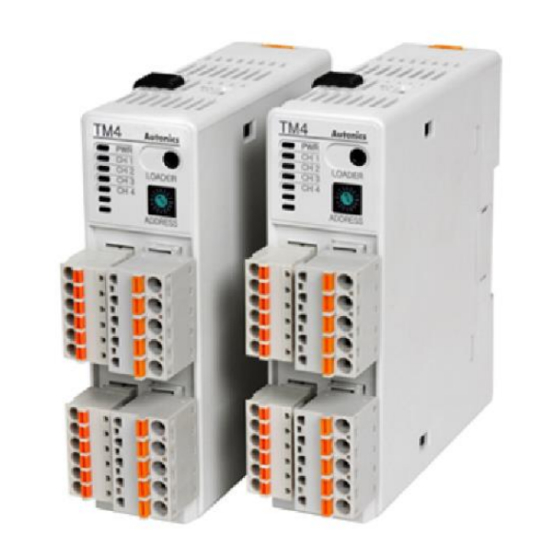
Solution Overview Solution description Autonics TM4 device from the TM series is a multi-channel PID temperature controller, capable of controlling various type of power controllers thanks to its build-in SSR driver or relay output and simultaneously controlling up to 4 elements, (up to 2 elements for the TM2 type). It has also build-in serial Modbus connection through RS-485 pins. -
Page 10: Solution Components And Version
XG-5000 v4.22 LS product. Release 2017.09.29 XGT Series(Cnet) LS product Solution architecture Bridges should be addded between the “Tx+“ and “Rx+“ pins and between the “Tx-“ and “Rx-“ pins of the XGL communication module. © Copyright Reserved Autonics Co., Ltd. -
Page 11: Tm4 Communication Settings
TM4 Communication Settings Devices from the TM series do not have graphic interface; To change the devices’ settings, we need to use the device management program from Autonics: DAQMaster. Set the desired Modbus address thanks to the ‘Communication address’ switches, this address... - Page 12 2 TM4 Communication Settings The TM temperature controller has been properly set. © Copyright Reserved Autonics Co., Ltd.
-
Page 13: Xgt Project Settings
To synchronize the modules information, stop the PLC processing by selecting [Online] – [Change Mode] – [Stop]. If you cannot stop the PLC with this method, change the ‘RUN/STOP’ switch of the PLC CPU from ‘RUN’ to ‘STOP’. © Copyright Reserved Autonics Co., Ltd. - Page 14 ‘OK’ to close the ‘I/O information’ window. When I/O synchronizing is completed, communication modules will be added under [Network Configuration] – [Undefined Network] in the project tree. Double-click on the ‘XGL-CH2A/B’ communication module. © Copyright Reserved Autonics Co., Ltd.
- Page 15 Operation Channel 2 Use P2P Mandatory mode In ‘Advanced Settings’ tab set as below, then click ‘OK’. Item Channel 2 Data bit Advanced Stop bit settings Parity bit NONE © Copyright Reserved Autonics Co., Ltd.
- Page 16 In the project tree, right click on the ‘XGL-CH2A/B’ communication module, and select [Add Item] – [P2P Communication]. Select ‘1’ and click ‘OK’ In the project tree, double click on the newly created ‘P2P Channel’ under communication 10th module – [P2P 01]. © Copyright Reserved Autonics Co., Ltd.
- Page 17 Please refer to the XG5000 documentation for procedures on Ladder program creation and other method to write project to a XGT device. Please refer to the TM documentation for the complete list of Modbus registers and information on Modbus functions. © Copyright Reserved Autonics Co., Ltd.
- Page 18 3 XGT Project Settings © Copyright Reserved Autonics Co., Ltd.
-
Page 19: Data Exchange Example
D115 Setting Value Write 0x403E8 D116 Auto-Tuning CH2 Write 0x4044C D117 In this example, we will set the communication address: - of the XGT device to 0 - of the TM4 device to 1 © Copyright Reserved Autonics Co., Ltd. -
Page 20: Xg5000 Program
1 command No. of variables fixed Data size Enter value if read several word registers in 1 command Destination station Enable To define Modbus ID Destination station number Modbus ID of the targeted device © Copyright Reserved Autonics Co., Ltd. - Page 21 Click on ‘Setting’ button and set as following, then click ‘OK’. Item Setting Note Read area 0x303E8 TM register to read/write data Save area D110 XGT register to save/read data Address Auto filled Fixed by XG5000 Set the other table elements as following: © Copyright Reserved Autonics Co., Ltd.
-
Page 22: Ladder Program
4 Data Exchange Example 4.2.2 Ladder program Create the following ladder program: To set and monitor values: To manage reading flags: © Copyright Reserved Autonics Co., Ltd. - Page 23 We will not describe how to create a Ladder program under XG 5000 in this document. Please refer to the XG 5000 documentation for more information. The project has been properly created, we need then to download the complete project to the XGT device by selecting [Online] – [Write], then clicking ‘OK’. © Copyright Reserved Autonics Co., Ltd.
-
Page 24: Data Exchange Test
Activate the CH1 Auto-Tuning function (M0815=D115=0x40064 = 1): In the ‘//write values’ section, double click on the ‘M0815’ variable, set to ‘1’ to start the function or ‘0’ to stop it, and click ‘OK’: © Copyright Reserved Autonics Co., Ltd. - Page 25 The CH1 or/and CH2 LED indicator will turn on if PV is lower than SV. The CH1 or/and CH2 LED indicator will flash with 1 sec period if the Auto Tuning function has been activated. © Copyright Reserved Autonics Co., Ltd.
- Page 26 4 Data Exchange Example © Copyright Reserved Autonics Co., Ltd.
-
Page 27: Appendix
For each configuration, the procedure under DAQ Master is the same: Start DAQ Master and select TM4 device (or TM2 depending of your model) under [Support Device List] - [AUTONICS] in the left tab menu. © Copyright Reserved Autonics Co., Ltd. - Page 28 Fixed to 9600 if using SCM-US cable Check Parity None (default) / Need to try different settings Odd / Even Stop bit 1 / 2 (default) Need to try different settings Bit Per Byte Fixed © Copyright Reserved Autonics Co., Ltd.
- Page 29 ‘OK’. Rem: - search time can be reduced by changing searching range according to your device setting - if using the SCM-US cable, all addresses can be used; set the range to 1~1. © Copyright Reserved Autonics Co., Ltd.
- Page 30 ‘My System’ architecture and select ‘Read All Parameters’. When the synchronisation has been done, you can access and customize your device parameters in the ‘Property’ window at the left side of DAQ Master. © Copyright Reserved Autonics Co., Ltd.
-
Page 31: Troubleshooting
Please, stop the PLC processing by selecting [Online] – [Change Mode] – [Stop]. If you cannot stop the PLC with this method, change the ‘RUN/STOP’ switch of the PLC CPU from ‘RUN’ to ‘STOP’. © Copyright Reserved Autonics Co., Ltd. - Page 32 6 Troubleshooting © Copyright Reserved Autonics Co., Ltd.
Need help?
Do you have a question about the TM-XGT and is the answer not in the manual?
Questions and answers