MTS Sensors Temposonics R Series Operation Manual
Magnetostrictive linear position sensors
Hide thumbs
Also See for Temposonics R Series:
- Operation manual (23 pages) ,
- Datasheet (16 pages) ,
- Datasheet (15 pages)

Related Manuals for MTS Sensors Temposonics R Series


Summary of Contents for MTS Sensors Temposonics R Series
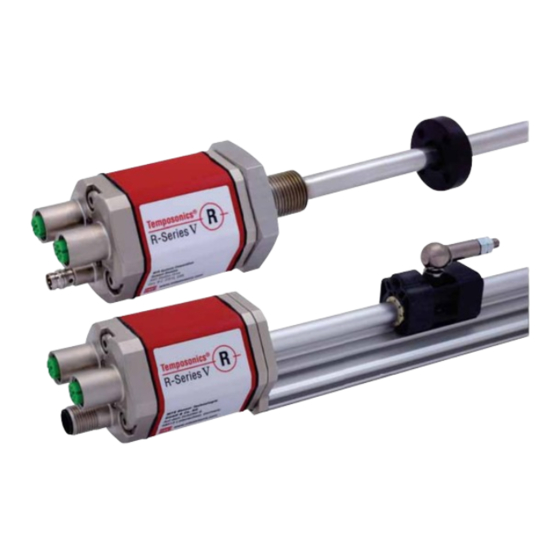
- Page 1 ® Temposonics Magnetostrictive Linear Position Sensors R-Series V PROFINET IO RT & IRT ® Temposonics Operation Manual...
-
Page 2: Table Of Contents
R-Series V Profinet RT & IRT Temposonics ® Operation Manual Table of contents 1. Introduction ..............................3 1.1 Purpose and use of this manual ................................3 1.2 Used symbols and warnings ..................................3 2. Safety instructions ............................. 3 2.1 Intended use ......................................3 2.2 Foreseeable misuse .................................... -
Page 3: Introduction
This product may be used only for the applications defined under item 1 and only in conjunction with the third-party devices and components recommended or approved by MTS Sensors. As a prerequsite of proper and safe operation the product requires correct transport, storage, mounting and commissioning and must be operat ed with utmost care. -
Page 4: Installation, Commissioning And Operation
Fill the outer packaging around the sensor completely to prevent 2.4 Safety instructions for use in explosion-hazardous areas damage during transport. The sensor is not suitable for operation in explosion-hazardous areas. 2/ See also applicable MTS Sensors terms of sales and delivery on: www.mtssensors.com I 4 I... -
Page 5: Identification
R-Series V PROFINET IO RT & IRT Temposonics ® Operation Manual 3. Identification 3.1 Order code of Temposonics ® a Sensor model f Connection type 8 2 × M12 female connectors (D-coded), 1 × M12 male connector (A-coded) 6 2 × M12 female connectors (D-coded), b Design 1 ×... -
Page 6: Order Code Of Temposonics
R-Series V PROFINET IO RT & IRT Temposonics ® Operation Manual 3.2 Order code of Temposonics ® a Sensor model f Connection type 8 2 × M12 female connectors (D-coded), 5 Rod 1 × M12 male connector (A-coded) 6 2 × M12 female connectors (D-coded), b Design 1 ×... -
Page 7: Nameplate
R-Series V PROFINET IO RT & IRT Temposonics ® Operation Manual 3.3 Nameplate RP5SA0200M01D581U402 Order code MAC: 00-03-CA-00-58-F6 MAC address S/N: 18020203 Serial number 12JAN2018 Date of Production Fig. 1: Example of nameplate of a R-Series V RP5 sensor with PROFINET output 3.4 Approvals •... -
Page 8: Product Description And Commissioning
(position) variable in the fields of automated systems and mechanical engineering. Strain pulse detected by converter Principle of operation and system construction The absolute, linear position sensors provided by MTS Sensors rely on the company’s proprietary Temposonics ® magnetostrictive Fig. -
Page 9: Styles And Installation Of Temposonics Rp5
R-Series V PROFINET IO RT & IRT Temposonics ® Operation Manual 4.2 Styles and installation of Temposonics RP5 RP5 M A V e ample Connection type D58 (connector output) (0.2) Sensor electronics housing Null one Stroke length Dead one 48 (1.89) 25…6350 66/71* (1.1) -
Page 10: Styles And Installation Of Temposonics Rh5
R-Series V PROFINET IO RT & IRT Temposonics ® Operation Manual 4.3 Styles and installation of Temposonics RH5 Sensor electronics housing Null one Stroke length Dead one 25…7620 63.5/66* (0.67) (2.68) (2.01) (1…300) (2.5/2.6*) MS R NS RN M18×1.5-6g ¾"-16 UNF-3A (0.98) * Stroke length >... - Page 11 R-Series V PROFINET IO RT & IRT Temposonics ® Operation Manual Sensor electronics housing Null one Stroke length Dead one 25…5900 73.6 (0.67) (2.68) (2.01) (1…232) (2.9) MS R NS RN M22×1.5-6g (0.98) (2.09) A V R 5 base unit (only for replacement) e ample Connection type D58 (connector output) Sensor electronics housing Null one...
- Page 12 R-Series V PROFINET IO RT & IRT Temposonics ® Operation Manual Installation of RH5 with threaded flange In the case of threaded flange M18×1.5-6g or M22×1.5-6g, provide Fix the sensor rod via threaded flange M18×1.5-6g, M22×1.5-6g or a screw hole based on ISO 6149-1 (Fig. 11). See ISO 6149-1 for further ¾"-16 UNF-3A.
-
Page 13: Magnet Installation
R-Series V PROFINET IO RT & IRT ® Temposonics Operation Manual Centered mounting 4.4 Magnet installation of block magnet Typical use of magnets Air gap: 3 ±2 Magnet ypical sensors 8 ±2 (0.12 ±0.08) (0.31 ±0.08) Ring magnets Rod model •... - Page 14 R-Series V PROFINET IO RT & IRT Temposonics ® Operation Manual RH5 with ring magnet/U-magnet Start- and end positions of the position magnets Consider the start and end positions of the position magnets during Sensor electronics housing the installation. To ensure that the entire stroke length is electrically Reference edge of mounting usable, the position magnet must be mechanically mounted as follows.
-
Page 15: Alignment Of The Magnet With The Option "Internal Linearization
A sensor with internal linearization is delivered with the magnet with which the sensor was calibrated during production. In order to achieve the best possible result, MTS Sensors recommends to operate the RP5 with magnet sliders sensor with the supplied magnet. -
Page 16: Replacement Of Sensor
R-Series V PROFINET IO RT & IRT Temposonics ® Operation Manual For RP5 PROFINET sensors with the U-magnet applies: 4.6 Replacement of sensor • Install the magnet until the marking on the magnet points to the sensor electronics housing. The base unit of the sensor model RH5-B is replaceable as shown •... -
Page 17: Electrical Connections
R-Series V PROFINET IO RT & IRT Temposonics ® Operation Manual 3. Insert the new base unit. 4.7 Electrical connections Mount the ground lug on a screw. Tighten the screws. Placement of installation and cabling have decisive influence on the sensor‘s electromagnetic compatibility (EMC). Hence correct installation of this active electronic system and the EMC of the entire system must be ensured by using suitable metal connectors, shielded cables and grounding. - Page 18 R-Series V PROFINET IO RT & IRT Temposonics ® Operation Manual Connector wiring Connect the sensor directly to the control system, indicator or other evaluating systems as follows: Port 1 Port 2 Power supply Fig. 26: Location of connections Si na Si na onn tor onn tor...
-
Page 19: Frequently Ordered Accessories For Rp5 Design
R-Series V PROFINET IO RT & IRT Temposonics ® Operation Manual 4.8 Frequently ordered accessories for RP5 design – Additional options available in our Accessories Guide 551 444 osition a n ts 15.2 57 (2.24) (1.65) (0.6) (1.69) (0.94) (1.69) (0.55) (0.55) 49 (1.93) -
Page 20: Frequently Ordered Accessories For Rh5 Design
R-Series V PROFINET IO RT & IRT Temposonics ® Operation Manual 4.9 Frequently ordered accessories for RH5 design – Additional options available in our Accessories Guide 551 444 osition a n ts Ø 32.8 (Ø 1.29) Ø 4.3 Ø 32.8 Ø... -
Page 21: Frequently Ordered Accessories For Profinet Output
R-Series V PROFINET IO RT & IRT Temposonics ® Operation Manual 4.10 Frequently ordered accessories for PROFINET output – Additional options available in our Accessories Guide 551 444 onn tors Si na onn tors (2.05) (2.09) (1.7) (0.24) (0.63) od d a onn tor onn tor nd ap od d... - Page 22 R-Series V PROFINET IO RT & IRT Temposonics ® Operation Manual po r a onn tor art no strai t pi tai art no art no art no Material: PVC jacket; gray Material: PUR jacket; gray Features: Shielded Operating temperature: Cross section: 3 ×...
-
Page 23: Operation
R-Series V PROFINET IO RT & IRT Temposonics ® Operation Manual 5. Operation 5.2 LED Status 5.1 Initial start-up A diagnostic display on the lid of the sensor informs about the current status of the sensor. The R-Series V is equipped with three LEDs: The position sensor R-Series V PROFINET transfers position and •... -
Page 24: Supported Network Functions
R-Series V PROFINET IO RT & IRT Temposonics ® Operation Manual 6. Programming and configuration in the TIA Portal 6.1 General Information This instruction describes as an example the integration and R-Series V sensor with PROFINET ® programming of a Temposonics into the TIA Portal (Totally Integrated Automation Portal) of Siemens AG. - Page 25 R-Series V PROFINET IO RT & IRT Temposonics ® Operation Manual The R-Series V PROFINET supports both RT mode and IRT mode. The Different input modules are available for the R-Series V PROFINET sensor is set to the respective mode during connection setup with the with MTS profile.
- Page 26 R-Series V PROFINET IO RT & IRT Temposonics ® Operation Manual • Velocity: This module contains the velocity of a magnet. Afterwards • Wrong Number of Magnets (Setting of the alarm behavior when you must assign a magnet to this module. the actual number of position magnets differs from the specified number of position magnets) Drag the selected module into the "Device Overview"...
- Page 27 R-Series V PROFINET IO RT & IRT Temposonics ® Operation Manual • Reading the values of the input module "Sensor status": To read the information from the input module "Sensor status", drag this module into the "Device Overview" window. The module "Sensor status"...
- Page 28 R-Series V PROFINET IO RT & IRT Temposonics ® Operation Manual The status of the switching points is reported in parallel to the position values or velocity values via the PROFINET protocol. A magnet must be specified for each switching point, which is used to check the respective limit.
- Page 29 R-Series V PROFINET IO RT & IRT Temposonics ® Operation Manual • Reading additional information regarding the sensor status: In parallel to the position values and the velocity values, the sensor can output further information on the sensor status via the PROFINET protocol. This information is stored in an array with 19 Integer32 values, which you call via the address API 0 Slot 0 Subslot 1 Index 2000.
-
Page 30: Parameter Description For Encoder Profile V4.2
R-Series V PROFINET IO RT & IRT Temposonics ® Operation Manual 6.3 Parameter description for encoder profile V4.2 To enable the control to access the sensor data isochronously, the isochronous mode must be activated in the "Advanced options" After you have created a project, you can include the sensor via its section of the "General"... - Page 31 R-Series V PROFINET IO RT & IRT Temposonics ® Operation Manual Standard telegram 81 Standard telegram 81 uses 4 bytes for output data from the IO controller to the sensor and 12 bytes of input data from the sensor to the IO-controller. Output data from the IO controller (control sensor) IO Data...
- Page 32 R-Series V PROFINET IO RT & IRT Temposonics ® Operation Manual Control word 2 (STW2_ENC) Value Significance Comments 0…6 – – Reserved Fault acknowledge (0 The fault signal is acknowledged with a positive edge; the sensor reaction to a fault depends on the type of fault. 8, 9 –...
- Page 33 R-Series V PROFINET IO RT & IRT Temposonics ® Operation Manual The selected telegram must be dragged into the "Device Overview" • Extrapolation Mode (Setting of the sensor behaviour in case of window. In the example shown, telegram 84 was selected and assi- oversampling) gned to slot 1 subslot 2 (Fig.
- Page 34 R-Series V PROFINET IO RT & IRT Temposonics ® Operation Manual • Accepting negative preset values: You can use the "Config Flags • Setting the parameter P65005: You can use the "Config Flags 1" 1" entry to set that negative preset values are also accepted in entry to set how to change the parameter P65005.
- Page 35 R-Series V PROFINET IO RT & IRT Temposonics ® Operation Manual In addition to the manufacturer-specific parameters, there are the • Maximum master sign-of-life failures: following standard parameters according to the encoder profile: Specifies the number of allowed failures of the masters sign-of- life.
-
Page 36: Tempolink Smart Assistant With R-Series V Profinet
8.2 Maintenance The sensor is maintenance-free. 8.3 Repair Repairs of the sensor may be performed only by MTS Sensors or a repair facility explicitly authorized by MTS Sensors. For return see chapter "2.6 Return" on page 4. 8.4 List of spare parts No spare parts are available for this sensor. -
Page 37: Technical Data
R-Series V PROFINET IO RT & IRT Temposonics ® Operation Manual 10. Technical data 10.1 Technical data Temposonics R-Series V RP5 Output Interface PROFINET RT PROFINET IRT version 2.3 Data protocol Data transmission rate 100 MBit/s (maximum) Measured value Position, velocity/option: Simultaneous multi-position and multi-velocity measurements up to 30 magnets Measurement parameters 0.5…100 μm (selectable) Resolution: Position... -
Page 38: Technical Data Temposonics R-Series V Rh5
R-Series V PROFINET IO RT & IRT Temposonics ® Operation Manual 10.2 Technical data Temposonics R-Series V RH5 tp t Interface PROFINET RT PROFINET IRT version 2.3 Data protocol Data transmission rate 100 MBit/s (maximum) Measured value Position, velocity/option: Simultaneous multi-position and multi-velocity measurements up to 30 magnets as r nt para t rs Resolution: Position... - Page 39 Please include safety data sheets of the substances, if applicable. Please include safety data sheets of the substances, if applicable. consult MTS Sensors to determine measures to be taken before consult MTS Sensors to determine measures to be taken before shipment.
- Page 40 R-Series V Profinet RT & IRT Temposonics ® Operation Manual 12. Appendix II 1. Dimensions and tolerances based on ANSI Y14.5-1982. 2. MTS has extracted all pertinent information from MS33649 to generate this document. 3. PD must be square with surface B within 0.005 FIM across 2.250 dia minimum.
-
Page 41: Glossary
R-Series V Profinet RT & IRT Temposonics ® Operation Manual 13. Glossary as rin ir tion When moving the position magnet, the position and velocity values increase in the measuring direction. the velocity of one magnet can be measured and transferred •... - Page 42 MTS, Temposonics and Level Plus are registered trademarks of MTS Systems Corporation in the United States; MTS SENSORS and the MTS SENSORS logo are trademarks of MTS Systems Corporation within the United States. These trademarks may be protected in other countries. All other trademarks are the property of their respective owners. Copyright © 2021 MTS Systems Corporation. No license of any intellectual property rights is granted.
Need help?
Do you have a question about the Temposonics R Series and is the answer not in the manual?
Questions and answers