Danfoss VLT FC Series Operating Instructions Manual
Option panel
Hide thumbs
Also See for VLT FC Series:
- Installation manual ,
- Service manual (370 pages) ,
- Operating manual (26 pages)
Table of Contents
Advertisement
Quick Links
Download this manual
See also:
Installation Manual
Advertisement
Table of Contents

Subscribe to Our Youtube Channel
Related Manuals for Danfoss VLT FC Series


Summary of Contents for Danfoss VLT FC Series
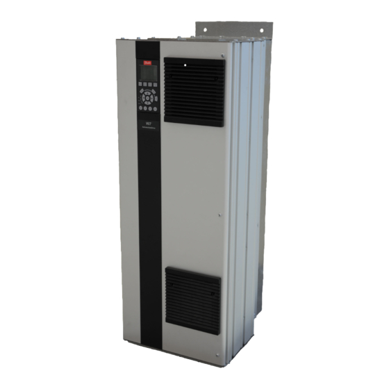
- Page 1 MAKING MODERN LIVING POSSIBLE Operating Instructions ® FC Series Option Panel...
-
Page 3: Table Of Contents
3.2.1 Lifting 3.2.2 Hoist or Overhead Lift 3.2.3 Forklift 3.2.4 Shipping Weights 3.2.5 Cooling 3.3 Electrical Installation 3.4.1 Component Identification 3.4.2 Wire and Cable Access 3.4.3 Wire Size 3.4.4 Wire Type Rating ® MG14I102 - VLT is a registered Danfoss trademark... - Page 4 6.1.10 ECB Run Permissive 6.1.11 ECB Overload 6.1.12 ECB Safety Interlock 6.1.13 ECB Common Run/Stop 6.1.14 ECB Advanced Fire Mode 6.1.15 ECB Fault Reporting 7 Non-bypass Component Functions 7.1.1 Power Fusing ® MG14I102 - VLT is a registered Danfoss trademark...
- Page 5 Contents Option Panel Operating Instructions 7.1.2 Reactors 7.1.3 Disconnects 7.1.4 Motor Options 7.1.5 Contactor Motor Select 8 Start Up Troubleshooting 8.1.1 Option Panel Alarm and Warnings ® MG14I102 - VLT is a registered Danfoss trademark...
-
Page 6: Introduction
A variable frequency drive regulates the speed and lation and operation of the vertical panel used in operation of an electric motor(s). The drive is conjunction with a Danfoss variable frequency drive (VFD). programmable and offers many features and savings To enable efficient handling of the equipment,... -
Page 7: Typical Bypass Operation
Bypass options are programmed through the drive’s fire mode parameters. See fire mode section of the drive manual and support materials for available options. ® MG14I102 - VLT is a registered Danfoss trademark... -
Page 8: Bypass Platform Configurations
Contactor motor select option option fuse Control SMPS transformer Motor 1 Secondary 24 V DC fuse internal use 120 V for internal use Motor 2 Illustration 1.2 Bypass Circuit with Options ® MG14I102 - VLT is a registered Danfoss trademark... -
Page 9: Switch Mode Power Supply (Smps)
1.6.2 Drive Disconnect (Optional) Two-position (ON/OFF) rotary switch disconnects main AC line input power to the drive only. ® MG14I102 - VLT is a registered Danfoss trademark... -
Page 10: Option Panel Configurations
Illustration 1.5 shows drive with bypass or up to two of the following: • Contactor motor selection • dU/dt filter or input AC line reactor (NEMA 1 only) • Dual motor control ® MG14I102 - VLT is a registered Danfoss trademark... -
Page 11: Option Panel Voltage And Frame Ratings
208-230 40-60 40-50 460-480 100-125 75-100 575-600 100-125 75-100 Table 1.8 Frame C2 FC 102/202 FC 302 [V AC] [hp] [hp] 460-480 150-200 125-150 575-600 150-200 125-150 Table 1.9 Frame D1 ® MG14I102 - VLT is a registered Danfoss trademark... -
Page 12: Pre-Installation
Table 2.1 Legend to Illustration 2.1 damaged or lost in transit, you do so at your own risk and expense. Danfoss IS WILLING TO ASSIST YOU TO COLLECT Ensure that the model number and power match the order CLAIMS FOR LOSS OR DAMAGE, BUT WILLINGNESS ON and intended use for the drive. -
Page 13: Installation Site Check
In such environments, use TYPE 12 enclosures to limit the exchange of outside air into the option enclosure. Extremely harsh environments may require a higher level of protection. ® MG14I102 - VLT is a registered Danfoss trademark... -
Page 14: Installation
• Remove skid and other supports from under drive. • For floor mounting applications, a floor mounting kit is available from Danfoss specifically designed to anchor drive to floor. ® MG14I102 - VLT is a registered Danfoss trademark... -
Page 15: Forklift
UNITS. OPTIONS CAN ADD OR REDUCE WEIGHT OF UNIT. 1.5 in min. Frame Tier 1 [lbs] Tier 2 [lbs] Tier 3 [lbs] A2-A3 1037 Table 3.1 Approximate Shipping Weights Illustration 3.4 Side Cooling Clearance, A-2 and A-3 Frames ® MG14I102 - VLT is a registered Danfoss trademark... -
Page 16: Electrical Installation
• Wear safety glasses whenever working on electric control or rotating equipment. NOTE MAKE ALL POWER CONNECTIONS WITH MINIMUM 75 ° C RATED COPPER WIRING FOR INSTALLATIONS IN NORTH AMERICA. ® MG14I102 - VLT is a registered Danfoss trademark... - Page 17 Control wiring should always be isolated from the high voltage power wiring. Avoid getting metal chips into electronics. Follow the connection procedures as illustrated in the drawing provided with the unit. ® MG14I102 - VLT is a registered Danfoss trademark...
-
Page 18: Component Identification
Customer terminal block Customer control connection terminal block on EMB1 and EMB2 control option Customer terminal block Customer control connection terminal block on EMB2 control option Table 3.3 Reference Designator Definitions ® MG14I102 - VLT is a registered Danfoss trademark... -
Page 19: Wire And Cable Access
Illustration 3.11 Tier 2 (Bottom view) NEMA 12 1 Drive 2 Conduit entry 3 Bypass Table 3.6 Legend to Illustration 3.11 ® MG14I102 - VLT is a registered Danfoss trademark... - Page 20 Installation Option Panel Operating Instructions Illustration 3.12 Tier 3 (Bottom View) NEMA 1 1 Drive 2 Conduit entry 3 Additional options 4 Bypass Table 3.7 Legend to Illustration 3.12 ® MG14I102 - VLT is a registered Danfoss trademark...
-
Page 21: Wire Size
Terminal Cap. [AWG] Terminal Cap. [AWG] Terminal Cap. [AWG] 0.50 0,75 7.50 300KCM 300KCM 300KCM 300KCM 300KCM 300KCM 300KCM 300KCM 300KCM 300KCM 300KCM 300KCM 300KCM Table 3.8 208 V Max Wire - Input ® MG14I102 - VLT is a registered Danfoss trademark... - Page 22 Maximum Wire Size [AWG] Maximum Wire Size [AWG] Maximum Wire Size [AWG] 0.50 0.75 300KCM 300KCM 300KCM 300KCM 300KCM 300KCM 300KCM 300KCM 300KCM 300KCM 300KCM 300KCM Table 3.10 230 V Max Wire - Input ® MG14I102 - VLT is a registered Danfoss trademark...
- Page 23 8 (0.5-10HP) 1/0 (15-30HP) 8 (0.5-10HP) 250KCM 1/0 (15-30HP) 1/0 (15-30HP) 4/0 (40-60HP) 8 (0.5-10HP) 4/0 (40-60HP) 1/0 (15-30HP) 250KCM 1/0 (15-30HP) 1/0 (15-30HP) Table 3.11 230 V Max Wire - Output ® MG14I102 - VLT is a registered Danfoss trademark...
- Page 24 350 KCM (DUAL) 350 KCM (DUAL) 350 KCM (DUAL) 250 KCM (DUAL) 350 KCM (DUAL) 350 KCM (DUAL) 350 KCM (DUAL) 350 KCM (DUAL) Table 3.12 460 V Max Wire - Input ® MG14I102 - VLT is a registered Danfoss trademark...
- Page 25 300 KCM (DUAL)(250-350HP) 8 (0.50-25HP) 300 KCM (DUAL) 300 KCM (DUAL)(250-350HP) 1/0 (30-75HP) 300 KCM (DUAL) 350 KCM (DUAL) 2/0 (DUAL)(200HP) 350KCM (100-125HP) Table 3.13 460 V Max Wire - Output ® MG14I102 - VLT is a registered Danfoss trademark...
- Page 26 250 KCM (DUAL) 250 KCM (DUAL) 250 KCM (DUAL) 250 KCM (DUAL) 350 KCM (DUAL) 350 KCM (DUAL) 350 KCM (DUAL) 250 KCM (DUAL) Table 3.14 600 V Max Wire - Input ® MG14I102 - VLT is a registered Danfoss trademark...
- Page 27 300 KCM (DUAL) 8 (0.50-30HP) (300-400HP) 300 KCM (DUAL) 300 KCM (DUAL) 300 KCM (DUAL) 350 KCM (DUAL) 1/0 (40-75HP) (300-400HP) 2/0 (DUAL)(250HP) 350KCM (100-125HP) Table 3.15 600 V Max Wire - Output ® MG14I102 - VLT is a registered Danfoss trademark...
-
Page 28: Wire Type Rating
Although not as common, the input power may be an isolated source. All drives may be used with an isolated input source as well as with ground reference power lines. ® MG14I102 - VLT is a registered Danfoss trademark... -
Page 29: Grounding (Earthing)
Keep the ground wire connections as short as possible. Illustration 3.14 Control Terminals Location 1 EIA-485 terminal 2 Jumper wire 3 Control terminals 4 Grounded restraining clips Table 3.16 Legend to Illustration 3.14 ® MG14I102 - VLT is a registered Danfoss trademark... -
Page 30: Serial Communication Bus Connection
61. 3.4.11 Programming Serial communication point maps, parameter settings, and other details for bypass option functionality are included in the serial communication materials supplied with the unit. ® MG14I102 - VLT is a registered Danfoss trademark... -
Page 31: Start Up
Confirm that incoming power voltage matches drive label voltage and motor nameplate voltage. For multiple winding motors, motor must be wired on run winding, not start winding. ® MG14I102 - VLT is a registered Danfoss trademark... -
Page 32: Inspection Before Start Up
Look for any unusual amount of vibration the equipment may be subjected to. The panel should be mounted solidly or the use of shock mounts employed. Table 4.1 Inspection Before Start Up ® MG14I102 - VLT is a registered Danfoss trademark... -
Page 33: Start Up Procedure
Up Troubleshooting for isolation procedures. c. Check full load amps on input terminals L1, L2, and L3. Verify that current is within FLA of drive and balanced ® MG14I102 - VLT is a registered Danfoss trademark... - Page 34 Exercise safety circuit and verify that unit stops running. Exercise start/stop circuit and verify that unit starts and stops with system in auto mode of operation. ® MG14I102 - VLT is a registered Danfoss trademark...
-
Page 35: Electromechanical Bypass (Emb) Operation
Electromechanical Bypass (E... Option Panel Operating Instructions 5 Electromechanical Bypass (EMB) Operation Illustration 5.1 Customer-side EMB2 Control Card Terminal Connctions ® MG14I102 - VLT is a registered Danfoss trademark... - Page 36 Table 5.1 EMB2 Control Card Terminal Functions 1 Switch S103 autobypass timer 2 Terminal X56 3 Terminal X55 4 Terminal X58 Table 5.2 Legend to Illustration 5.2 Illustration 5.2 EMB2 Control Card ® MG14I102 - VLT is a registered Danfoss trademark...
- Page 37 Table 5.4 lists common functions for controlling a motor(s) with a bypass and the typical terminal connections used. Commands enable drive functions. Status reports describe conditions but do not enable a function. ® MG14I102 - VLT is a registered Danfoss trademark...
-
Page 38: Emb(0) And Emb1
Normally open, dry contact CMS Motor 1, close to select CMS Common Normally open, dry contact CMS common Input Normally open, dry contact CMS Motor 2, close to select Table 5.7 EMB(0) Terminal Functions ® MG14I102 - VLT is a registered Danfoss trademark... - Page 39 Start Common run/stop Input 5-00 Digital I/O Mode External Interlock 5-01 Terminal 27 Mode Input External Interlock 5-12 Terminal 27 Digital External Interlock External Interlock Input Table 5.9 EMB1 Parameter Settings ® MG14I102 - VLT is a registered Danfoss trademark...
-
Page 40: Emb Auto Bypass
Enable auto bypass by closing one or more DIP switches on switch S103 located on the bypass control card. (Times are approximate.) • All OFF = no auto bypass operation • 1-3 ON = 15 s delay (minimum) ® MG14I102 - VLT is a registered Danfoss trademark... -
Page 41: Emb Run Permissive
A Class 20 overload is standard with a variable resetting. The overload offers a manual (hand) or setting for motor current. Test and reset buttons are also ® MG14I102 - VLT is a registered Danfoss trademark... -
Page 42: Emb Safety Interlock
For the EMB(0) or EMB1, drive terminals terminals 1 and 2. 1 (common), 2 and 3 report faults with 2 open and 3 closed in the fault condition. ® MG14I102 - VLT is a registered Danfoss trademark... -
Page 43: Emb Switches
(M3 contactor), or disconnected from both. The test position allows for operation in bypass while still providing power to the drive (M1 and M3). See Illustration 5.6. Illustration 5.6 Basic 3-contactor Bypass Functions ® MG14I102 - VLT is a registered Danfoss trademark... -
Page 44: Electronically Controlled Bypass (Ecb) Operation
Programming options for drive terminals are seen by pressing [Main Menu] or [Quick Menu] on the LCP. Parameter menus appear in the LCP display. The arrow keys are used for navigating through the parameter lists. ® MG14I102 - VLT is a registered Danfoss trademark... - Page 45 Auto bypass 5-40 Function Relay (0) Start Command Active Run Permissive 5-40 Function Relay (0) Off Delay 0.00 S Run Permissive Table 6.2 Parameter Group 5-** Digital In/Out Factory Default Settings ® MG14I102 - VLT is a registered Danfoss trademark...
-
Page 46: Drive Control Terminals
RS-485 interface. When the drive is connected to an RS-485 serial communication bus, a drive control card switch is provided for termination resistance. ON for termination and OFF for no termination. See drive support materials for details. Table 6.3 Drive Control Terminals Functions ® MG14I102 - VLT is a registered Danfoss trademark... -
Page 47: Ecb Control Card
See Table 6.5 for ECB control card terminal types and functions. Illustration 6.3 ECB Control Card Terminal X58 Terminal X56 Terminal X57 Terminal X59 Table 6.4 Legend to Illustration 6.3 ® MG14I102 - VLT is a registered Danfoss trademark... - Page 48 Electronically Controlled B... Option Panel Operating Instructions Illustration 6.4 ECB Control Card Terminal Connections ® MG14I102 - VLT is a registered Danfoss trademark...
- Page 49 N.O. contact for running in bypass or drive Relay output for user N.O. contact for running in bypass or drive Relay output for user 3-12 Factory use only Table 6.5 ECB Card Terminals ® MG14I102 - VLT is a registered Danfoss trademark...
-
Page 50: Ecb Drive Or Bypass Selection
When running in drive mode, press [OK] on LCP to activate bypass mode or press [Cancel] to remain in drive mode. In bypass, motor will run at full speed. Illustration 6.9 ® MG14I102 - VLT is a registered Danfoss trademark... -
Page 51: Ecb Programming
• [Off Reset] allows the user to stop the motor locally from the LCP. Press [Off Reset] to stop the motor locally, either in drive or bypass mode. ® MG14I102 - VLT is a registered Danfoss trademark... -
Page 52: Ecb Mode Of Operation
• Press [Off Reset] on the LCP to prevent operation of the motor. ® MG14I102 - VLT is a registered Danfoss trademark... - Page 53 The External Interlock Bit will be true when an External Interlock fault is detected. Manual Bypass Override The Manual Bypass Override Bit will be true when the Manual Bypass Override input is true. Table 6.9 31-10 Bypass Status Word Word Bit Definitions ® MG14I102 - VLT is a registered Danfoss trademark...
-
Page 54: Bypass Status Word Bit Examples
If the timer completes its cycle before the fault clears, the panel trips into bypass mode and the motor runs at constant full speed from line input voltage. Illustration 6.14 Bypass Trip Time Delay ® MG14I102 - VLT is a registered Danfoss trademark... -
Page 55: Ecb Run Permissive
The higher the overload, the shorter the time. terminals selected, and program the terminals for run request. • Wire the input run command to the drive input terminals selected, and program the terminals for run permissive. ® MG14I102 - VLT is a registered Danfoss trademark... -
Page 56: Ecb Safety Interlock
A factory installed jumper between situations. The fire mode function is built-in. See the drive X57 terminals 1 and 2 allows the unit to operate when no support materials for programmable options. ® MG14I102 - VLT is a registered Danfoss trademark... -
Page 57: Ecb Fault Reporting
The drive monitors the ECB card communication and detects when communication stops. An ECB card failure or communication error could cause this. Contact Danfoss for technical support if this happens. Fault reporting function setup •... -
Page 58: Non-Bypass Component Functions
Two-position (ON/OFF) rotary switch, padlock bypass. The motors may be of the same or different hp, compatible, with three fuses, one on each phase, built into the switch. For safety, the switch must ® MG14I102 - VLT is a registered Danfoss trademark... -
Page 59: Contactor Motor Select
Operation • The panel mounted contactor motor select switch (SW2) has three positions: Motor 1/Auto/Motor 2. It is operated by hand for manual operation. The ® MG14I102 - VLT is a registered Danfoss trademark... -
Page 60: Start Up Troubleshooting
Indicates the number of sec. left until the system automatically activates Bypass Mode. Time delay can be adjusted using 31-02 Bypass Trip Time Delay. Table 8.2 Panel Status Display (ECB only) ® MG14I102 - VLT is a registered Danfoss trademark... - Page 61 Perform startup and verify that drive current is within specifications. If not, reduce the load on the motor. Loose connections Perform pre-startup check for loose Tighten loose connections. connections. Table 8.3 Fault Table ® MG14I102 - VLT is a registered Danfoss trademark...
- Page 62 Rotation incorrect in bypass, drive or Motor rotation is backwards in drive Perform motor rotation procedure in rotation both mode, bypass mode, or both. 4 Start Up. incorrect Table 8.4 Fault Table ® MG14I102 - VLT is a registered Danfoss trademark...
- Page 63 U to V, V to W, and W to U. option panel output terminal, it is a problem with the option panel. Contact the factory for assistance. Table 8.5 Fault Table ® MG14I102 - VLT is a registered Danfoss trademark...
- Page 64 130R0496 MG14I102 Rev. 2012-11-14 *MG14I102*...
Need help?
Do you have a question about the VLT FC Series and is the answer not in the manual?
Questions and answers